
June 2011 Vol. 238 No. 6
Features
Keystone Pipelines Cathodic Protection Journey Spans Three Years And 2,147 Miles
The Keystone Pipeline is a 2,147-mile (3,456-km) pipeline that transports crude oil from Hardisty, Alberta, to U.S. Midwest markets at Wood River and Patoka in Illinois, and ultimately to Cushing, OK.
On June 30, 2010, TransCanada (TCPL) began commercial operation of the first phase of the Keystone Pipeline System.
Keystone’s first phase was highlighted by the 537-mile (864-km) conversion of a natural gas pipeline to a crude oil pipeline, and the construction of a bullet line that brings the crude oil non-stop from Canada through North Dakota, South Dakota, Nebraska, Kansas, Missouri and Illinois to market hubs in the U.S. Midwest (Figure 1).

In late 2007, Cimarron Engineering teamed with TCPL Corrosion Specialists to serve as Keystone lead designers and project managers for the cathodic protection (CP) system development and installation program. Aside from the task of preparing CP design specifications, the primary function of the CP team was to work with multiple project design teams, regional and national regulators, construction managers, regional contractors, and multiple foreign pipeline operators.
Unlike a majority of projects where CP design is started after the structure is built and commissioned, Keystone integrated CP design into the pipeline project during early design phases. Early CP integration was required to optimize CP system performance and ensure CP systems would be commissioned within six months of pipeline being placed in service. As challenging as the process was, Keystone achieved its CP commitments on schedule, with many lessons learned for future projects.
CP Becomes A Project Activity. As part of Keystone’s U.S. pipeline design and construction, the CP system was to be installed and commissioned within six months of the pipeline being in service.
Accordingly, CP would need to be planned and integrated into the project design long before pipeline construction commenced. To avoid potential inconsistencies associated with CP design being conducted on a regional basis, Keystone assembled a central CP team to develop a single system-wide CP plan.
Design Team Interfacing. The first step for the Keystone CP team was to establish communication protocols with the many project participants involved. This included Canadian and U.S. pipeline design teams, a pipeline conversion team for the more than 800 km of existing gas pipeline in Canada, a facility design team for all pump stations and terminals, numerous consultants, and global and regional construction management supervisors.
Communicating with and understanding the needs and design input of each of these project participants was undoubtedly the most time-consuming and challenging role of the CP team, yet essential for project success.
Project CP Needs. The CP team concluded that the conversion of the existing gas pipeline in Canada would have little effect on existing CP system infrastructure and performance. The addition of new pump stations along a multiple pipeline gas transmission corridor with existing extensive CP systems would not substantially increase current requirements; CP enhancements would be handled via post construction diagnostic testing and remedial action. However, disconnection of the new oil line from the other gas pipelines (and existing CP current sources) at stations and crossover sites resulted in the need for installing CP continuity bonds, which were undertaken as part of the conversion construction program at minimal cost and effort.
More than 2,000 km of new-build NPS 30 fusion bond epoxy coated mainline in Canada and the U.S. would require dedicated CP systems. Pump stations were designed with above-grade product piping, so the only below grade piping requiring CP at the stations were short sections of NPS 3 and NPS 4 drain piping. This design assessment, along with the complex configuration of the side valves at the stations, determined the mainline and the stations would be electrically continuous, resulting in common CP systems to protect the mainline, as well as the minimal station piping.
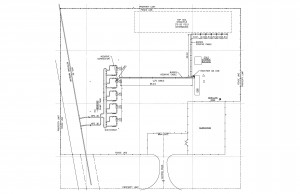
The preliminary CP plan determined current sources spaced at 30-mile (50-km) intervals would meet both CP capacity and current distribution needs. An overlay of the CP needs with the pipeline route showed that pump stations were typically spaced at 60-mile (100-km) intervals with a remote operated mainline valve (RMLV) at the midpoint between pump stations. The CP plan was based on installing impressed current CP systems at each pump station and the midpoint RMLV between pump stations. These locations provided readily available access to AC power for each rectifier, as well as available enclosed space and security protection for all CP equipment (see Figure 2 for Pump Station layout).
In locations where Keystone is adjacent to existing TCPL pipelines in Canada, the CP plan included installing negative drain leads during pipeline construction to minimize the post-construction effort to bond Keystone to existing TCPL CP systems. This eliminated the need for RMLV midpoint CP systems in Canada, reducing the capital cost for the CP plan. In the U.S., Keystone paralleled a 1950s’ oil transmission pipeline for approximately 500 miles (800 km). As this older pipeline had an extensive network of CP systems, the Keystone Pipeline would be at risk to interference from its high output rectifiers. As such, pre-construction design planning included mitigative provisions such as galvanic anodes and interference connection points to address interference immediately after construction and before Keystone’s impressed current systems would be commissioned.
CP Compatible Facility Design. Since pump stations are integral to the pipeline, the goal was to minimize the current demands of the stations and valve sites by implementing design options which would electrically isolate non-essential structures from the CP systems. At each pump station, more than 200 below-ground structural steel piles were planned; the CP team worked with the station-design team to utilize di-electric pile caps and non-conductive support surfaces wherever possible to minimize CP current flow to the piles. The net benefit reduced the total current flow to the piles from more than 30 amperes to less than 10 amperes.
The CP team also requested site-grounding cables to be di-electrically coated, and to use steel grounding rods where possible, or ensure copper ground rods were a minimum of 15 feet from protected piping. At valve sites, equipment supports were embedded in concrete and actuators with di-electric valve connectors were selected to decouple the CP system from the valve site AC service and minimize CP current flow to local electrical grounding grids. Such design options were implemented during initial construction, reducing troubleshooting or remediation once the pipeline CP system was placed into service.
Installation Schedule. Having the CP system available within six months of pipeline start-up raised concerns about dealing with winter CP construction. A large portion of the pipeline is situated in northern climates where winter CP construction results in substantial cost increases and quality control challenges during installation. The CP team decided to start and complete CP installations while final pipeline and station construction was still in progress. One methodology included scoping portions of the CP installation within the general contractor scope. This minimized ground disturbance and excavation permitting, as well as mechanical installation work for the CP contractor. All buried negative CP cables were installed in low-voltage cable trenches during electrical installations, and rectifier mounting brackets and AC service supplies were addressed prior to the CP contractor installing rectifiers and anodes.
Additional efforts included specifying the CP contractor install anodes and positive cables prior to final site grading to minimize soil stripping and clean-up. However, based on timing of CP installations at many pump stations, the CP contractor was required to trench CP cables without mechanical equipment. This became the most inefficient part of the CP installations as specific ground disturbance and backfill requirements were required. A future improvement for consideration is to ensure all below-grade cables at pump stations are installed by the general contractor prior to site grading, and while mechanical excavation is permitted.
Installation And Commissioning. Operations for Keystone began June 30, 2010 when all of the 11 impressed current systems at the valve sites were installed and energized, and 27 of the 29 impressed current CP systems at the pump stations had been installed and energized. The remaining two CP systems were completed within six months of the in-service date. The TCPL corrosion team has been undertaking CP commissioning surveys to comply with regulatory survey requirements as well as to balance CP system performance to ensure the pipeline and associated facilities are adequately protected.
Keystone CP Accomplishments. Integrating CP design into the project plans three years before the pipeline was placed into service realized the following achievements:
1. Minimized current flow to non essential structures by implementing electrical isolation during initial construction, and optimizing electrical ground system and CP layouts.
2. Optimized CP infrastructure by developing a simplified desktop CP plan without time-consuming post construction current requirement testing. The design provided an appropriately sized CP system to achieve adequate CP levels during commissioning without installing redundant or unnecessary CP equipment. Wherever possible, provisions to connect to existing CP infrastructure were included in the CP plan.
3. The pipeline construction plans included details for all CP bonds and interference test stations to foreign operators so all CP test leads were installed prior to backfilling. Excavation costs are the largest single component of overall test lead and bond-installation costs.
4. By integrating CP into the master construction schedule and plan, some CP components were installed during pipeline or facility construction, allowing CP installations to be planned and completed well before the six-month compliance window. This optimized the time and materials costs for supplying and installing CP materials by providing ample lead time for each site.
As Keystone continues to expand, the implementation of the Keystone CP model will result in further cost savings in the installation and timely commissioning of effective CP systems.
Authors
Dennis Zadery is a pipeline integrity specialist with Cimarron Engineering, a Calgary based engineering consulting company which specializes in the development, design, installation and integrity maintenance of pipeline systems and station facilities. Contact care/of Ryan Hutchinson, ryan_hutchinson@cimarron.ab.ca.
Brad Woloschuk is a senior corrosion engineer with TransCanada.

Comments