
March 2011, Vol. 238 No. 3
Features
Enhanced Pipeline Seam Assessment
The ability to use a single inline inspection (ILI) tool in one run to record multiple datasets is becoming increasingly important to pipeline owners and operators as they face a growing need to inspect their assets for a wide variety of defects.
This one-tool, one-run ability not only saves time and expense for both the operator and the inspection service provider, it also generates datasets that are recorded with the same distance, making subsequent correlation of results during the post-run analysis more accurate and efficient.
During the past several years, “combo” tools incorporating multiple technologies – such as deformation coupled with magnetic flux leakage (MFL) – have become the norm. As a result, many operators have come to expect, and even rely on, the enhanced data possible through use of multiple technologies. A recent advance in seam assessment technology has made it easier than ever to combine multiple technologies into a single inspection tool.
Spiral Fields
Many seam assessments on pre-1970 electric resistance welded (ERW) pipe have been performed by transverse field inspection (TFI) tools; that is, MFL oriented in the transverse or circumferential direction. As shown in Figure 1, inducing magnetism in this manner requires the tool to be configured with two offset magnetizers to accomplish 100% coverage of the pipe wall.
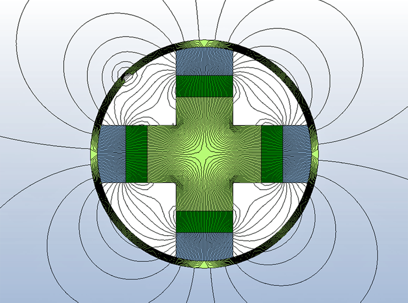
T.D. Williamson, Inc. (TDW) recently developed a new approach to seam assessments based on induction of magnetism using a “spiral” or “oblique” field, creating what is called a spiral magnetic flux leakage (SMFL) tool. As shown in Figure 2, this patent-pending spiral design provides complete pipe-wall inspection in a single, compact magnetizer rather than the two magnetizers required by TFI tools. This, in turn, facilitates the ability to not only inspect long seams, it also allows fusion with traditional high-resolution MFL for improved classification of seam-weld anomalies, as well as detection and quantification of other longitudinally oriented anomalies. It also offers traditional metal loss assessment by utilizing multiple datasets – all on a single inspection tool.

Figure 2: Boundary element model (BEM) of “spiral” or “oblique” field. This design allows 100% coverage of the pipe wall with a single magnetizer.
Multiple Datasets
From the initial idea stage of the SMFL concept, the plan was always to incorporate multiple data-sensing technologies on a single tool to provide a comprehensive view of a pipeline. These multiple technologies would include: 1) mapping; 2) high-resolution deformation for bore measurement and strain calculations; 3) inside diameter/outside diameter (ID/OD) sensors incorporated on deformation arms for verification of internal/external metal loss classification and details on internal surface conditions, i.e. discrimination of debris fields from dents or other bore reductions; and 4) residual or low-field sensors capable of detecting hard spots, the “halo-effect” due to dent re-rounding, and other mechanical flaws.
All of these technologies are included in addition to MFL and SMFL on the multiple dataset platform. Inspection using varying magnetic fields and other sources, including deformation, not only improves detection but, more importantly, anomaly identification. Multiple views of the same anomaly in different datasets, from the same inspection run, provide an increasingly clear picture, resulting in superior analysis and anomaly characterization.

Figure 3: Dent with Metal Loss: From left to right, residual (RES) sensors reveal remnant strain known as a “halo-effect” left by denting; deformation (DEF) data with cross-section depicts the dent; MFL data inclusive of ID/OD reveals the dent – the red hue represents detection on ID/OD sensors from sensor “lift-off”; SMFL data reveals metal loss in the dent that was not detected in MFL.
For example, the anomaly shown in Figure 3 demonstrates the benefit of multiple dataset technology. Availability of only the deformation and MFL data would simply identify a dent at this location. Deformation data reveals a dent at approximately seven o’clock and is confirmed in the MFL data including ID/OD overlay. The red hue indicates sensor lift-off at the indication, which, along with deformation and MFL data, confirms the dent. The residual data indicates additional strain induced by the dent outside of the specific dent area. Notice the apparent strain that extends around the circumference beyond the dent area itself. The dent is located at the green oval; additional strain is indicative of the red background surrounding the dent. Note that the strain extends around the circumference.
What was not clear in the previous four datasets (deformation, MFL, ID/OD and residual) becomes quite evident upon review of SMFL data. There is a signature indicating the dent, though closer analysis reveals a gauss change. This gauss change confirms metal loss at the dent, metal loss which went undetected by MFL due to the geometry of the indication.
Compact Configuration
The multiple dataset platform is not simply for pipelines requiring seam assessments. Operators can utilize SMFL with any planned MFL inspection for a view of the longitudinal axis in conjunction with standard metal loss inspection for enhanced detection. Identifying metal loss, axial gouging, narrow axial corrosion, other longitudinal anomalies in the pipe body, and hard spots and seam anomalies no longer requires multiple tool runs. This powerful combination of technologies is available in a compact configuration.
Though keeping tool length to a minimum is partially achieved by the single-body SMFL magnetizer and utilization of all available canister space, the primary driver is the advancement in electronics packaging. One central processing unit (CPU) controls the entire system. Advantages of this innovation include: 1) a 3.3 times reduction in volume required for the CPU; 2) significant power savings (by 4.5 times) from the previous platform; 3) increased run time (by 4.5 times); 4) greater data storage capacity (at 5 times the previous system); 5) synchronization of all datasets; and 6) significant increase in sensor inputs.

Figure 4: An 8-inch multiple dataset configuration including spiral MFL, deformation, ID/OD, MFL and residual sensors (SMFL+DEF+ID/OD+MFL+RES). The drive section contains odometers to measure distance traveled. This tool measures 93 inches and features 396 sensors.
As shown in Figure 4, each tool module contains some form of measurement technology, thus eliminating the need for unnecessary canisters that increase overall length. The 8-inch multiple dataset tool, for example, is 93 inches long and includes odometers, SMFL, deformation, ID/OD, MFL and residual sensors. The total sensor count is 396 for all technologies on this platform.
Eliminating Guesswork
Analysis of MFL and SMFL signatures simultaneously eliminates guesswork in calling seam-weld anomalies, which means less time and money spent by the pipeline operator making unnecessary digs. Figure 5 shows MFL data on the left and SMFL data on the right. The anomaly within the long-seam seen in SMFL was identified as a crack-like feature from a previous TFI inspection. Note that this anomaly is clearly visible in the MFL data, which indicates it is volumetric in nature rather than crack-like.
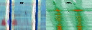
Figure 5: MFL and SMFL data from an inspection. The vertical lines are steel bands from a composite wrap placed on the metal loss anomaly. Based on the original TFI survey, 15 locations were taped and recoated or had composite wrap installed after removing the original coating and finding metal loss rather than crack-like anomalies.
By utilizing MFL data in conjunction with SMFL from the same inspection run, classification of the anomaly becomes clear as a metal loss feature that happens to be in the seam weld rather than a crack-like feature in the seam. In this example, there were 14 other similarly characterized anomalies that were excavated based on the TFI inspection; all 15 would have been correctly eliminated from the dig list utilizing SMFL and the multiple dataset technology.
To date, more than 1,000 miles of pipeline have been successfully inspected using SMFL technology. As described in this article, capturing multiple datasets in a single inspection run provides clarity of anomalies, which translates into greater accuracy of results delivered to the pipeline operator. The technology has proven to eliminate unnecessary seam anomaly excavations as compared to TFI, and to offer improved identification of other longitudinally oriented anomalies. More specific details on the spiral or oblique field can be found in the paper titled “Oblique Field Magnetic Flux Leakage Inline Survey Tool: Implementation and Results,” authored by James Simek, Jed Ludlow and Phil Tisovec. It was presented at the 2010 International Pipeline Conference.
Author
Chuck Harris is the general manager of TDW’s Western Hemisphere Pipeline Integrity Operation and based in Houston. Harris has 18 years experience in the inline inspection industry. He started in data analysis in 1993, later migrating to technical sales. He joined TDW in 2003 in Applications Sales Support and held several sales roles prior to his current responsibility. Harris holds a bachelor’s degree in business from LeTourneau University.

Comments