
October 2010 Vol. 237 No. 10
Features
Efficiency And Operating Characteristics Of Centrifugal And Reciprocating Compressors
Reciprocating compressors and centrifugal compressors have different operating characteristics and use different efficiency definitions. This article provides guidelines for an equitable comparison, resulting in a universal efficiency definition for both types of machines. The comparison is based on the requirements in which a user is ultimately interested. Further, the impact of actual pipeline operating conditions and the impact on efficiency at different load levels is evaluated.
At first glance, calculating the efficiency for any type of compression seems to be straightforward: comparing the work required of an ideal compression process with the work required of an actual compression process. The difficulty is correctly defining appropriate system boundaries that include losses associated with the compression process. Unless these boundaries are appropriately defined, comparisons between centrifugal and reciprocating compressors become flawed.
We also need to acknowledge that the efficiency definitions, even when evaluated equitably, still don’t completely answer one of the operator’s main concerns: What is the driver power required for the compression process? To accomplish this, mechanical losses in the compression systems need to be discussed.
Trends in efficiency should also be considered over time, such as off-design conditions as they are imposed by typical pipeline operations, or the impact of operating hours and associated degradation on the compressors.
The compression equipment used for pipelines involves either reciprocating compressors or centrifugal compressors. Centrifugal compressors are driven by gas turbines, or by electric motors. The gas turbines used are, in general, two-shaft engines and the electric motor drives use either variable speed motors, or variable speed gearboxes. Reciprocating compressors are either low speed integral units, which combine the gas engine and the compressor in one crank casing, or separable “high-speed” units. The latter units operate in the 750-1,200 rpm range (1,800 rpm for smaller units) and are generally driven by electric motors, or four-stroke gas engines.
Efficiency
To determine the isentropic efficiency of any compression process based on total enthalpies (h), total pressures (p), temperatures (T) and entropies (s) at suction and discharge of the compressor are measured, and the isentropic efficiency ![]() s then becomes:
s then becomes:

(Eq. 1)
and, with measuring the steady state mass flow m, the absorbed shaft power is:
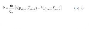
(Eq. 2)
considering the mechanical efficiency ![]() .
.
The theoretical (isentropic) power consumption (which is the lowest possible power consumption for an adiabatic system) follows from:
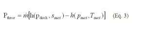
(Eq. 3)
The flow into and out of a centrifugal compressor can be considered as “steady state.” Heat exchange with the environment is usually negligible. System boundaries for the efficiency calculations are usually the suction and discharge nozzles. It needs to be assured that the system boundaries envelope all internal leakage paths, in particular recirculation paths from balance piston or division wall leakages. The mechanical efficiency ![]() , describing the friction losses in bearings and seals, as well as windage losses, is typically between 98 and 99%.
, describing the friction losses in bearings and seals, as well as windage losses, is typically between 98 and 99%.
For reciprocating compressors, theoretical gas horsepower is also given by Eq. 3, given the suction and discharge pressure are upstream of the suction pulsation dampeners and downstream of the discharge pulsation dampeners. Reciprocating compressors, by their very nature, require manifold systems to control pulsations and provide isolation from neighboring units (both reciprocating and centrifugal), as well as from pipeline flow meters and yard piping and can be extensive in nature. The design of manifold systems for either slow speed or high speed units uses a combination of volumes, piping lengths and pressure drop elements to create pulsation (acoustic) filters. These manifold systems (filters) cause a pressure drop, and thus must be considered in efficiency calculations. Potentially, additional pressure deductions from the suction pressure would have to made to include the effects of residual pulsations. Like centrifugal compressors, heat transfer is usually neglected
For integral machines, mechanical efficiency is generally taken as 95%. For separable machines a 97% mechanical efficiency is often used. These numbers seem to be somewhat optimistic, given the fact that a number of sources state that reciprocating engines incur between 8-15% mechanical losses and reciprocating compressors between 6-12% (Ref. 1: Kurz , R., K. Brun, 2007).
Operating Conditions
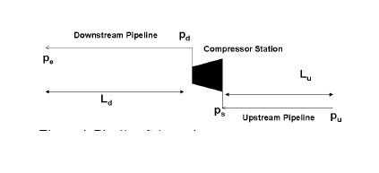
For a situation where a compressor operates in a system with pipe of the length Lu upstream and a pipe of the length Ld downstream, and further where the pressure at the beginning of the upstream pipe pu and the end of the downstream pipe pe are known and constant, we have a simple model of a compressor station operating in a pipeline system (Figure 1).
For a given, constant flow capacity Qstd, the pipeline will then impose a pressure ps at the suction and pd at the discharge side of the compressor. For a given pipeline, the head (Hs)–flow (Q) relationship at the compressor station can be approximated by
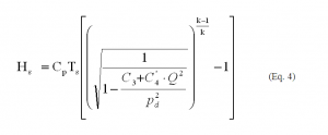
(Eq. 4)
where C3 and C4 are constants (for a given pipeline geometry) describing the pressure at either ends of the pipeline, and the friction losses, respectively (Ref. 2: Kurz, R., M. Lubomirsky, 2006).
Among other issues, this means that for a compressor station within a pipeline system, the head for a required flow is prescribed by the pipeline system (Figure 2). In particular, this characteristic requires the capability for the compressors to allow a reduction in head with reduced flow, and vice versa, in a prescribed fashion. The pipeline will therefore not require a change in flow at constant head (or pressure ratio).
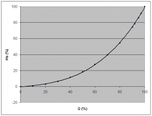
Figure 2: Station Head-Flow relationship based on Eq. 4.
In transient situations (for example during line packing), the operating conditions follow initially a constant power distribution, i.e. the head flow relationship follows:

(Eq. 5)
and will asymptotically approach the steady state relationship (Ref. 3: Ohanian, S., R. Kurz, 2002).
Compressor Control
Based on the requirements above, the compressor output must be controlled to match the system demand. This system demand is characterized by a strong relationship between system flow and system head or pressure ratio. Given the large variations in operating conditions experienced by pipeline compressors, an important question is how to adjust the compressor to the varying conditions, and, in particular, how does this influence the efficiency.
Centrifugal compressors tend to have rather flat head vs. flow characteristic. This means that changes in pressure ratio have a significant effect on the actual flow through the machine (Ref. 4: Kurz, R., 2004). For a centrifugal compressor operating at a constant speed, the head or pressure ratio is reduced with increasing flow.
Controlling the flow through the compressor can be accomplished by varying the operating speed of the compressor. This is the preferred method of controlling centrifugal compressors. Two shaft gas turbines and variable speed electric motors allow for speed variations over a wide range (usually from 40-50% to 100% of maximum speed or more). It should be noted, that the controlled value is usually not speed, but the speed is indirectly the result of balancing the power generated by the power turbine (which is controlled by the fuel flow into the gas turbine) and the absorbed power of the compressor.
Virtually any centrifugal compressor installed in the past 15 years in pipeline service is driven by a variable speed driver, usually a two-shaft gas turbine. Older installations and installations in other than pipeline service sometimes use single-shaft gas turbines (which allow a speed variation from about 90-100% speed) and constant speed electric motors. In these installations, suction throttling or variable inlet guide vanes are used to provide means of control.
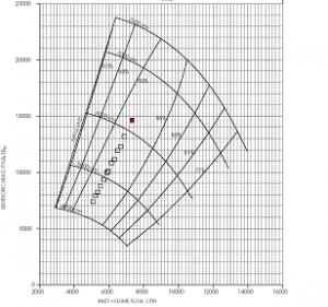
Figure 3: Typical pipeline operating points plotted into a typical centrifugal compressor performance map.
The operating envelope of a centrifugal compressor is limited by the maximum allowable speed, the minimum flow (surge flow), and the maximum flow (choke or stonewall) (Figure 3). Another limiting factor may be the available driver power.
Only the minimum flow requires special attention, because it is defined by an aerodynamic stability limit of the compressor. Crossing this limit to lower flows will cause a flow reversal in the compressor, which can damage the compressor. Modern control systems prevent this situation by automatically opening a recycle valve. For this reason, virtually all modern compressor installations use a recycle line with control valve that allows the increase of the flow through the compressor if it comes near the stability limit. The control systems constantly monitor the operating point of the compressor in relation to its surge line, and automatically open or close the recycle valve if necessary. For most applications, the operating mode with an open, or partially open recycle valve is only used for start-up and shut-down, or for brief periods during upset operating conditions
Assuming the pipeline characteristic derived in Eq. 4, the compressor impellers will be selected to operate at or near its best efficiency for the entire range of head and flow conditions imposed by the pipeline. This is possible with a speed (N) controlled compressor, because the best efficiency points of a compressor are connected by a relationship that requires approximately (fan law equation):

(Eq. 6)
For operating points that meet the above relationship, the absorbed gas power Pg is (due to the fact that the efficiency stays approximately constant):
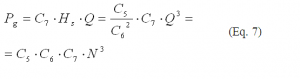
(Eq. 7)
As it is, this power-speed relationship allows the power turbine to operate at, or very close to its optimum speed for the entire range. The typical operating scenarios in pipelines therefore allow the compressor and the power turbine to operate at its best efficiency for most of the time. The gas producer of the gas turbine will, however, lose some thermal efficiency when operated in part load.
Figure 3 shows a typical real world example: Pipeline operating points for different flow requirements are plotted into the performance map of the speed controlled centrifugal compressor used in the compressor station.
Reciprocating compressors will automatically comply with the system pressure ratio demands, as long as no mechanical limits (rod load, power) are exceeded. Changes in system suction or discharge pressure will simply cause the valves to open earlier or later. The head is lowered automatically because the valves see lower pipeline pressures on the discharge side and/or higher pipeline pressures on the suction side. Therefore, without additional measures, the flow would stay roughly the same – except for the impact of changed volumetric efficiency which would increase, thus increasing the flow with reduced pressure ratio.
The control challenge lies in the adjustment of the flow to the system demands. Without additional adjustments, the flow throughput of the compressor changes very little with changed pressure ratio. Historically, pipelines installed many small compressors and adjusted flow rate by changing the number of machines activated. This capacity and load could be fine-tuned by speed or by a number of small adjustments (load steps) made in the cylinder clearance of a single unit. As compressors have grown, the burden for capacity control has shifted to the individual compressors.
Load control is a critical component to compressor operation. From a pipeline operation perspective, variation in station flow is required to meet pipeline delivery commitments, as well as implement company strategies for optimal operation (i.e., line packing, load anticipation). From a unit perspective, load control involves reducing unit flow (through unloaders or speed) to operate as close as possible to the design torque limit without overloading the compressor or driver. The critical limits on any load map curve are rod load limits and HP/torque limits for any given station suction and discharge pressure. Gas control generally will establish the units within a station that must be operated to achieve pipeline flow targets. Local unit control will establish load step or speed requirements to limit rod loads or achieve torque control.
The common methods of changing flow rate are to change speed, change clearance, or de-activate a cylinder-end (hold the suction valve open). Another method is an infinite-step unloader, which delays suction valve closure to reduce volumetric efficiency. Further, part of the flow can be recycled or the suction pressure can be throttled, thus reducing the mass flow while keeping the volumetric flow into the compressor approximately constant.
Control strategies for compressors should allow automation, and be adjusted easily during the operation of the compressor. In particular, strategies that require design modifications to the compressor (for example: re-wheeling of a centrifugal compressor, changing cylinder bore, or adding fixed clearances for a reciprocating compressor) are not considered here. It should be noted that with reciprocating compressors, a key control requirement is to not overload the driver or to exceed mechanical limits.
Operation
The typical steady state pipeline operation will yield an efficiency behavior as outlined in Figure 4. This figure is the result of evaluating the compressor efficiency along a pipeline steady state operating characteristic. Both compressors would be sized to achieve their best efficiency at 100% flow, while allowing for 10% flow above the design flow. Different mechanical efficiencies have not been considered for this comparison.
The reciprocating compressor efficiency is derived from valve efficiency measurements in Ref. 5 (Noall, M., W. Couch, 2003) with compression efficiency and losses due to pulsation attenuation devices added. The efficiencies are achievable with low speed compressors. High speed reciprocating compressors may be lower in efficiency.

Figure 4: Compressor Efficiency at different flow rates based on operation along a steady state pipeline characteristic.
Figure 4 shows the impact of the increased valve losses at lower pressure ratio and lower flow for reciprocating machines, while the efficiency of the centrifugal compressor stays more or less constant.
Conclusions
Efficiency definitions and comparison between different types of compressors require close attention to the definition of the boundary conditions for which the efficiencies are defined as well as the operating scenario in which they are employed. The mechanical efficiency plays an important role when efficiency values are used to calculate power consumption. If these definitions are not considered, discussions of relative merits of different systems become inaccurate and misleading.
Authors
Rainer Kurz is the manager of systems analysis at Solar Turbines Inc. in San Diego, CA. His organization is responsible for predicting compressor and gas turbine performance, for conducting application studies, and for field performance testing. He attended the Universitaet der Bundeswehr in Hamburg, Germany, where he received the degree of a Dr.-Ing in 1991. He has contributed numerous articles about turbomachinery topics to publications and is an ASME fellow.
Bernhard Winkelmann is a manager in the Marketing and Product Strategies Organization for Solar Turbines, San Diego, with special emphasis on gas compressor products and applications. He has more than 20 years of experience in the turbomachinery industry in Germany, Belgium and the U.S. He received his Dipl. Ing. degree from the University of Bochum in 1989.
Saeid Mokhatab, based in Dartmouth, NS, Canada, is an internationally recognized expert in the field of natural gas engineering with a particular emphasis on design and operations of both single-phase and multiphase gas transmission pipelines. A regular contributing editor to P&GJ, he has participated as a senior consultant in various pipeline EPC projects and has published more than 180 academic and industry oriented papers on related topics. He can be reached at: saeid_mokhatab@hotmail.com.
References
1 Kurz , R., K. Brun, 2007, “ Efficiency Definition and Load Management for Reciprocating and Centrifugal Compressors,” ASME Paper GT2007-27081.
2 Kurz, R., M. Lubomirsky, 2006, “Asymmetric Solution for Compressor Station Spare Capacity,” ASME Paper 2006-90069.
3 Ohanian, S., R. Kurz, 2002, “Series or Parallel Arrangement in a Two-Unit Compressor Station,” Trans. ASME JEng for GT and Power, Vol.124.
4 Kurz, R., 2004, “The Physics of Centrifugal Compressor Performance,” Pipeline Simulation Interest Group, Palm Springs, CA.
5 Noall, M., W. Couch, 2003, “Performance and Endurance Tests of Six Mainline Compressor Valves in Natural Gas Compression Service,” Gas Machinery Conference, Salt Lake City, UT.

Comments