
July 2010 Vol. 237 No. 7
Features
Effects Of Abnormal Conditions On Orifice Measurement Accuracy
Whenever one focuses on gas or fluid measurement, he or she will eventually discover an abnormal condition at a measurement station. Invariably someone will ask, “What effect will this have on measurement?” A student of measurement may spend years answering this question.
This and similar questions have generated many research studies. These studies have enabled us to better understand measurement abnormalities and to improve measurement procedures and standards. Even though we have made great strides in measurement, we will continue to ask this question. It is this question that has led to the development of this article. Instead of focusing on certain specific abnormalities, this article addresses the overall subject of measurement abnormalities and presents some investigative tools to assist attempts to answer the question. However, before we can understand measurement abnormalities, it is important to review proper or accurate measurement.
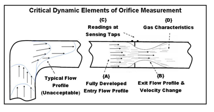
One of the oldest types of fluid measurement is based on the concept of forcing a pressure drop and velocity change with a specifically designed obstruction, and measuring the pressure change on either side of the obstruction, then applying these readings to a formula to calculate the fluid flow. This obstruction is called an orifice plate and the overall process is called orifice measurement. Orifice measurement includes an orifice, a meter tube, and sensing equipment. An orifice is installed in the meter tube. The sensing equipment measures the pressure change on both sides of the plate. The readings are used in a formula to calculate gas or fluid volume. The fluid flow changes caused by orifice measurement can be referred to as “critical dynamic elements of orifice measurement.” Figure 1 is a simple diagram of a measurement station and the dynamic elements.
The oil and gas industry quickly learned that not just any orifice or meter tube would produce accurate and repeatable results. Different pieces of equipment produce different results. Therefore, the industry conducted many studies to better understand these varying results. The studies were conducted at various flow laboratories under very controlled conditions to produce very repeatable results. They determined it was necessary to establish standards for the manufacture and installation of the equipment. The industry has developed a standard published by American Gas Association, “Orifice Metering of Natural Gas and Other Related Hydrocarbon Fluids, Parts 1 -4” (AGA 3). When the equipment was standardized, various orifices and meter tubes would produce the same dynamic element results.
Additional studies proved that abnormal conditions affect measurement because they alter one or more of the critical dynamic elements of the measurement process. Therefore, to understand what effect abnormal conditions have on the elements it is necessary to understand the four different critical dynamic elements of fluid measurement: (1) fully developed entry flow profile, (2) exit flow profile, (3) readings at the sensing taps, and (4) gas characteristics.
Fully Developed Entry Flow Profile
Measurement will not be accurate unless the gas is flowing properly. In the past it was assumed all gas flowed the same way down any pipe. However, we have learned that is not true because gas flow is affected by the piping, valves, and pipe configurations. The gas as it enters the orifice must be flowing straight, at a constant rate, and produce a symmetrical flow pattern. The molecules in the center of the pipe should be flowing faster than the gas at the pipe walls. The gas along the walls should all be flowing at about the same rate. The gas should not have any swirl or rotation. When gas flow meets these requirements, we say it is a “fully developed flow profile.” Item {A} in Figure 1 illustrates a “fully developed entry flow profile.”
Most gas flows through an elbow before it enters the meter tube. Figure 1 illustrates the gas flow through a 90 ° elbow. Gas will flow faster on the outer edge of the elbow and will maintain this pattern as it exits the elbow. This pattern will continue several feet down the pipe. If gas flows out of one elbow and into another elbow pointed in another direction before the flow has straightened out, it will develop a swirl to the elbow exit flow pattern. Other conditions such as protrusions in the pipe, ungrounded welds, rough or pitted pipe walls, and partially opened valves and obstructions will also adversely impact the flow profile.
The gas must be conditioned to flow properly to achieve the fully developed entry flow profile. A straight, smooth pipe can condition the gas flow. Studies indicate it takes straight, smooth pipe that is 136 times longer than the internal diameter (ID) of the pipe to condition or straighten out this type of flow pattern. A 2-inch meter tube would need 22 feet of upstream piping to meet this requirement. The upstream pipe on a 6-inch tube would need to be at least 68 feet long. Additional flow conditioners can be properly inserted into the upstream piping to condition the flow pattern and reduce the amount of upstream piping needed. AGA 3 Part 2 lists the requirements necessary to achieve a fully developed entry flow profile.
The fully developed entry flow will be altered and become unacceptable if anything disrupts it. If an abnormality is found within the meter tube piping upstream of the orifice and within the lengths stated in AGA 3, it can be safely assumed that the abnormality will adversely affect the entry flow profile and the resultant measurement. Most abnormal conditions found in the field affect the entry flow profile. Table 1 lists 29 conditions that have been identified to cause measurement error. The first 13 listed affect the entry flow profile.
Exit Flow Profile
The orifice plate is designed to change the flow pattern by forcing gas to the center of the pipe. This will increase the gas velocity as it leaves the plate bore. It will also cause a slight pressure drop on the downstream side of the plate. The plate must be designed and installed per the AGA 3 specifications to produce the proper exit flow profile. If the exit flow profile is not allowed to develop properly or is altered, the resulting measurement will be inaccurate.
It is well known that a plate installed backwards will cause a low volume because it does not allow the exit flow profile to develop properly. Leakage around the plate will cause a similar problem. Table 1 lists 9 abnormal orifice conditions and the recognized type of error. Over the years, we have modified the accepted criteria for an orifice plate. Recent studies have indicated that some of the previous criteria are incorrect. Additional studies may alter our existing requirements.
Table 1: Evaluation Of Typical Abnormal Conditions


The way to determine if any abnormality with the orifice causes measurement error is to consider the exit flow profile and question whether the abnormality affects it in any way. If there is any concern that it will, the abnormality must be eliminated.
Readings at the Sensing Taps
As stated, it is necessary to take pressure readings on either side of the orifice plate to use in the volume calculation equation. Studies have proven that it is very important to standardize the location of these sensing taps to collect accurate data. The current flow equation is based on the requirement that the sensing taps be located 1 inch from the face of the orifice. AGA 3 Part 2 gives strict requirements for these taps including placement, size, and roundness. The requirements are strict because this is a very critical part of the measurement process and small variations can have a major adverse effect on the readings.
It is important to recognize that the sensing taps include the connections to any sensing devices such as differential and pressure transmitters. The connections as well as the sensors can affect the reading that is taken from the sensing taps. When examining in search of possible problems, it is necessary to include these items in the sensing tap element.
There are many conditions which affect this element of measurement. Table 1 lists 7 recognized conditions that will affect the readings. The placement of the orifice is critical. If it is not centered between the sensing taps, it has the same effect as moving the taps. The resulting readings will be incorrect. The centering of the orifice in the tube also affects the sensing taps because any incorrect placement of the orifice will move the exit flow profile either to or away from the sensing taps and therefore affect the readings.
Liquids can have a major effect, changing the readings at the sensing taps. If liquid gets into the sensing taps or connected piping and sensors, a very small amount of liquid can have a major impact on the readings and resultant volume. Other conditions such as salt build up or tap freezes can have a large impact on the measurement.
An abnormal condition that affects the sensing tap element should be evaluated thoroughly because a small impact at the taps can have a major impact on measurement. If any abnormal condition is found it should be corrected in case it does have an adverse effect on the readings.
Gas Characteristics
The fourth critical dynamic element of orifice measurement is different than the other three because it is not impacted by the flow profiles. The gas characteristic element includes: gas temperature, gas density and gas composition. This information is used in the volume calculation just as the sensing tap readings are. If any of this information is incorrect, the resultant volumes will be incorrect.
In the past, the industry has not always recognized the impact of the gas characteristic element. Temperatures have been assumed rather than recorded. Samples have been taken haphazardly. Recent studies have highlighted the importance of this information and the necessity that it be accurate. This area should be reviewed carefully to determine if there are any possible problems. Samples need to be taken per the applicable API and GPA standards. Samples should be analyzed per the GPA procedures. Results should be compared to the meter history to verify that the information is correct.
Many times this area is not considered when reviewing for measurement abnormalities. It should become a part of the measurement review.
Measurement Standards
As mentioned, measurement standards became important to develop repeatable results from orifice metering that coincide with data used to create the flow volume calculation. These standards are reviewed on a frequent basis to continue to achieve accurate measurement. AGA 3 Part 2 is used for the manufacture and installation of the meter tube and orifice. These requirements are necessary to get an accurate entry flow profile, exit profile, and correct readings at the sensing taps. These requirements need to be used by the industry for all gas measurement processes. The author has been asked many times, “Is it necessary to follow all the requirements for this station?” Any time a measurement station is installed without meeting all the requirements, there is a good chance that a condition will exist then or in the future that will adversely affect one or more of the critical dynamic elements. Rather than trying to fudge on any of these requirements, we need to consider adding to the requirements to help ensure that the dynamic flow elements are correct.
Typical Abnormal Conditions
The table of typical abnormal conditions is a compilation of experiences from the author and from many other studies by respected experts in the industry who are much more knowledgeable than the author. The references at the end of the paper will list the sources of this information. This table is provided as a quick review of typical abnormalities and recognition of the dynamic element that is affected by the abnormality. The direction of error and comments are provided for information purposes only. It is not the absolute statement as to the overall impact of an abnormality but the observed result over many years.
There is an item missing from the table that many people would like to see added. This is the amount of error for each condition. This information is not included because it is very difficult to accurately evaluate the effect without conducting studies on the issue using the equipment, configuration, and flow criteria in a controlled laboratory environment. The presence of multiple abnormalities and the effects of the abnormalities on multiple dynamic elements make it very difficult to predict the expected error.
Even though one may not be able to predict the amount of error, one can fairly accurately review an abnormality and determine whether it might have an impact on any of the four elements. Listed below are some evaluation questions one can use in reviewing possible abnormalities:
(1) Does the abnormality occur within the dimensions of the meter tubes as prescribed by AGA 3 Part 2?
(2) Does the meter tube and orifice meet the AGA 3 Part 2 specifications?
(3) Are any of the specifications compromised by this possible abnormality?
(4) What critical dynamic element may be affected by the abnormality?
(5) How is it affected?
(6) Can the abnormality be removed and the flow tested or verified?
These investigative questions have been used by knowledgeable people to identify possible problems. As an example, let’s question whether liquid in a meter tube might affect measurement.
A small amount of liquid can coat the meter tube piping. This will have similar effects as rough pipe and therefore cause a possible low reading. If the liquid continued to increase to the point that it began to dam up at the plate, it might push the entry flow profile up towards the sensing tap and might adversely increase the pressure reading at the upstream tap. If liquid spills over the bore, it will change the bore size and dimension and will therefore alter the exit flow profile. This might increase the volume. The predictions above have been proved by research. William Johansen from Colorado Engineering Experiment Station, Inc. published a paper listing the result of his studies and those of other experts on entrained liquid. Their findings support our predictions.
Although it can be possible to predict potential errors, studies or calibrated flow tests will need to be conducted to absolutely determine the effect of an abnormal condition.
Conclusion
It is hoped this paper will provide some insight in evaluating potential abnormal conditions on measurement. Recognizing the four critical dynamic elements of orifice measurement may help some readers. Gas measurement really is not overly complicated once we understand the various elements.
The most important item to remember is the necessity to follow the AGA 3 Part 2 specifications regarding orifice measurement installations and operations. Compliance with these specs will eliminate many abnormal conditions seen in the field.
Acknowledgement
Based on an award-winning presentation made the author at the 2010 International School of Hydrocarbon Measurement conducted in May 11-13 in Oklahoma City.
The author–Dean Graves is corporate measurement administrator for Devon Energy Corporation, Oklahoma City. He has presented several papers and participated in multiple industry committees during his 30+ years in measurement. Ph: 405-228-8353, Email: Dean.Graves@dvn.com.
References
“Orifice Metering of Natural Gas and Other Related Hydrocarbon Fluids, Part 1 General Equations and Uncertainty Guidelines,” A.G.A. Report No. 3, Part 1 Third Edition, American Gas Association, Arlington, VA, Oct. 1990.
“Orifice Metering of Natural Gas and Other Related Hydrocarbon Fluids, Part 2 Specification and Installation Requirements,” A.G.A. Report No. 3, Part 2 Fourth Edition, American Gas Association, Washington, DC, Apr. 2000.
“Orifice Metering of Natural Gas and Other Related Hydrocarbon Fluids, Part 3 Natural Gas Applications,” A.G.A. Report No. 3, Part 3 Third Edition, American Gas Association, Arlington, VA, Aug. 1992.
Caldwell, S., “Effects of Abnormal Conditions on the Accuracy of Orifice Measurement,” 1974 International School of Hydrocarbon Measurement.
George, D.L., La Nasa, P.J., “Avoiding Orifice Meter Measurement Errors At Low Differential Pressures,” Pipeline and Gas Journal, Jan. 2002.
Husain, Z.D., “Theoretical Uncertainty of Orifice Flow Measurement,” Daniel Flow Products Inc., 1995
Johansen, W.R., “Effects of Abnormal Conditions on Accuracy of Orifice Measurement,” 2000 International School of Hydrocarbon Measurement.
Johansen, W.R., “Effects of Entrained Liquid on Orifice Measurements,” 2000 American School of Gas Measurement Technology.
Morrow, T.B., “Effects of Abnormal Conditions on Accuracy of Orifice Measurement,” 2004 International School of Hydrocarbon Measurement.
Seidl, W., “Installation & Operation Errors in Gas Measurement,” 1997 International School of Hydrocarbon Measurement.

Comments