
October 2009 Vol. 236 No. 10
Features
Cathodic Protection Is Moving To The Numerical Simulation Era
Operators are facing increased direct current (DC) interference issues due to denser pipeline networks. Furthermore, alternating current (AC) corrosion effects are augmented within more and more complex utilities corridors.
Cathodic protection (CP) systems for pipeline networks and storage tanks are evolving toward increasing complexity while new norms are calling for the usage of modeling techniques in the design process (e.g. NPR2760 for AC mitigation in The Netherlands).
With the development of external corrosion direct assessment (ECDA) techniques and standardization of integrity management databases, asset managers have been looking to develop tools to help prioritize surveys and maintenance schemes.
Evolution of numerical techniques (steered by mechanical industries such as automotive and aerospace) today allows modeling of the electro-chemical behavior of a CP system under complex interference conditions.
Applications
As for any engineering application, simulation models speed the process of optimizing designs and evaluating alternatives. Techniques are constantly evolving and benefits are maximized when simulation models are tightly linked with the process of field data gathering, leading to optimized integrity management activities. Examples of applications in pipelines and storage tank industries are:
- At the design stage, use of simulation models will depend on the complexity of the configuration and norms in application. Selection of the model approach will be linked to the type and quality of available data. Only advanced models (BEM and FEM, see hereafter) are able to optimize a CP system design through determining the IR-free potential.
- For mitigation, simulation models allow the detailed investigation of interferences of neighboring elements. Both DC and AC interferences can be modeled and optimal mitigation applied.
- For field surveys, sub-networks models are in use at the pre-assessment stage of DCVG campaigns. The model allows the virtual planning of the field survey and can help, for instance, to determine the optimal interruption scheme of rectifiers.
- For integrity management, complete networks can be modeled and fed with ECDA data. The model can then be utilized as the link between direct assessment information and continuous monitoring of “On” potentials. As the monitored values evolve, the simulation model allows determination of root causes and their effect on pipeline integrity, providing a powerful tool for prioritization of maintenance schemes.
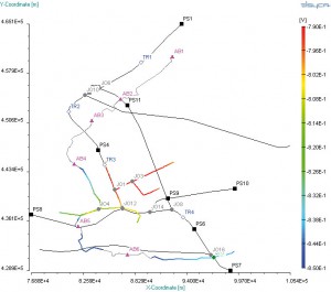
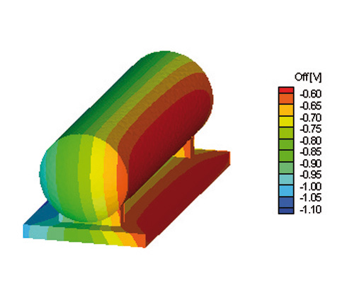
Figure 2: Simulation of the CP system of a buried pipeline network.
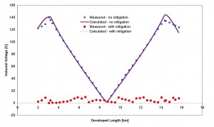
Figure 3: AC mitigation effect on a buried pipeline.
Challenges
In its most general form a CP system consists of a cathode (structure to be protected), an anode (that protects the cathode), an electrolyte (the soil) and the metallic connection between cathode and anode. For pipeline networks, these parameters vary along the developed length.
When designing a CP system for a pipeline network, the aim is to obtain a pipe-to-soil potential – or IR-free (IR = ohmic drop) potential on the entire structure – that is more negative than a certain minimum protection level.
According to the standards, this minimum level is taken at -0.85V vs. a copper-sulphate reference electrode (CSE) that needs to be placed directly adjacent to the pipeline in order to reduce the IR-drop in the soil and over the coating. However, in practice, due to the hidden character of the structure, it is usually impossible to put the reference electrode directly near the structure. Instead, the reference electrode is put at the ground (surface) level, directly above the structure, which can result in significant IR-drop errors.
Because simulation models do not have practical limitations of field measurements, the “true” IR-free potential can be calculated and compared to far-field, “On” and “Off” potentials (Figure 4).
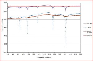
Figure 4: Comparative evolution of “On”, Remote Earth and IR-free potential along a protected pipeline.
Simulation accuracy always depends on the quality of the input data. Geometrical configurations of pipeline networks or storage tank structures are the most straightforward input parameters. Computer-aided design (CAD) files input for storage tank structures as well as Universal Transverse Mercator (UTM) format data (usually part of the GIS system) for pipeline networks are today commonly available and can be automatically imported in simulation tools.
Geotechnical data include Geotechnical Route Surveys and soil resistivity data performed through Soil Sampling Analysis (DIN 50929: Part 3). Depending on pipeline location and extension, large variations can be addressed. In addition, seasonal variations can impact soil resistivity values (e.g. permafrost cycles).
Structure and pipeline material characteristics, including coatings, will determine the polarization curves utilized by the solver. These data are tabulated and readily available for most material configurations. For existing networks, the evaluation of coating degradation will require field survey techniques such as direct current voltage gradient (DCVG).
DC and AC interferences are also influencing factors of importance for an accurate modeling of a CP system. DC interferences can have many origins such as third-party CP systems, compressors stations, railway networks and telluric currents. AC interference on the pipeline is linked to the inductive effect produced by neighboring HVAC transmission lines.
Techniques
The governing equations used in CP mathematical models originate from Ohm’s law and Laplace’s equation. Ohm’s law links the current density to the electric field while the Laplace equation provides the potential distribution taking into account soil and material resistivity.
A standard model in use for the pipeline industry is the so-called attenuation model. This model neglects both soil resistivity and pipeline polarization and assumes uniform coating resistance. The information provided by this model is limited to the pipeline potential to remote earth. Limited input required by the model enables its utilization as a pre-evaluation tool for the CP system configuration.
More advanced models do not neglect soil-resistivity influences in the domain and therefore require spatial discretization. Although combined techniques exist, two main approaches can be described, depending on the three-dimensional discretization method:
1. In the Boundary Element Method (BEM) only the outer surface of the geometry needs to be discretized. This approach allows modeling of large networks and environment with constant resistivity (such as seawater). Historically, BEM models have been developed for optimization of CP systems of ship hulls in marine applications. A limitation to this method is the difficulty in capturing complex 3D shapes in all details.
2. In the Finite Element Method, the discretization of the whole domain is performed, taking into account resistivity variation in all spatial points. The standard method widely utilized in mechanical design, it is more computer-intensive but has flexibility, which enables it to tackle geometrically complex configurations.
Operators introducing simulation techniques into their design and asset management processes need to combine focus both on the aspect of input parameters as well as on a careful selection of the model approach according the targeted output.
Authors
Jacques Parlongue is manager, corrosion protection, at Elsyca, which services the oil and gas industry with simulation tools for corrosion control.
Leslie Bortels is engineering manager at Elsyca. His scientific work is related to the development of simulation software for cathodic protection and electrodeposition processes. He is a NACE-certified CP specialist.

Comments