
October 2009 Vol. 236 No. 10
Features
Remote Monitoring Of Large CP System Saves Money In South America
Transportadora Brasileira Gasoduto Bolívia-Brasil S.A. (TBG) is saving about US$32,600/month in maintenance costs by employing a remote technique to monitor the cathodic protection system on the GASBOL pipeline.
Transportadora Brasileira Gasoduto Bolívia-Brasil S.A. (TBG) is saving about US$32,600/month in maintenance costs by employing a remote technique to monitor the cathodic protection system on GASBOL, the gas pipeline extending nearly 2,000 miles from Bolivia to Brazil.
Monitoring is conducted at a Central Station in Rio de Janeiro. The CP system uses 41 rectifiers mounted along the gas pipeline to control the electrochemical corrosion caused by the soil. Good performance by the system has allowed TBG to modify the inspection interval from once a week to once a month.
The GASBOL is a 32-inch pipeline running from the gas-producing fields of Rio Grande, Bolivia, to Canoas, Brazil. It distributes gas to five states in Brazil with a total length of 1,970 miles and a rated operating pressure of 1,420 psig. GASBOL is owned and operated by TBG S.A., a company whose shareholders are Petrobras, El Paso, Prisma, Shell, Total Fina, British Gas and YPFB.
Remote CP monitoring uses a remote terminal unit (RTU) to collect the information of a rectifier’s input/output voltage and output current. The RTU is able to store all the information available for 35 days and calculates soil resistance and system reliability. The RTU is fed by the rectifier. Communication with the control and supervision center (CSC) is accomplished using satellite telephony and can be initialized by either the RTU or the CSC.
Cathodic Protection
Corrosion is the result of an electromechanical reaction driven by a difference in electrical potential between two electrodes, an anode and a cathode, connected by an electronic path and immersed in the same electrolyte. In the case of uniform corrosion, a multitude of microscopic anodic and cathodic sites exist on the surface of the metal structure.
The rectifier is fundamental in an impressed current system as the rectifier provides the electrical current needed to polarize the entire pipeline to the potential electrolyte polarization equal to or more than -085 volts.
The concept of cathodic protection involves reducing the potential difference between the local anodic and cathodic sites to zero, resulting in zero corrosion current flow. This can be accomplished by impressing current onto the structure from an external electrode and polarizing the cathodic sites in an electronegative direction. As the potentials of the cathodic sites polarize toward the potentials of the anodic sites, corrosion current is reduced. When the potentials of all cathodic sites reach the open circuit potential of the most active anodic sites, corrosion is controlled at negligible rates on the structure. The structure is now the cathode of an intentional macroscopic corrosion cell.
The main components of an impressed current cathodic protection system are anodes, a power supplier (rectifier), wiring and connections. The anodes used in impressed current CP systems are different from those used in galvanic systems. Impressed current anodes are manufactured from materials that are consumed at low rates. Impressed current CP systems generally operate at higher current and driving voltage levels than galvanic anode CP systems.
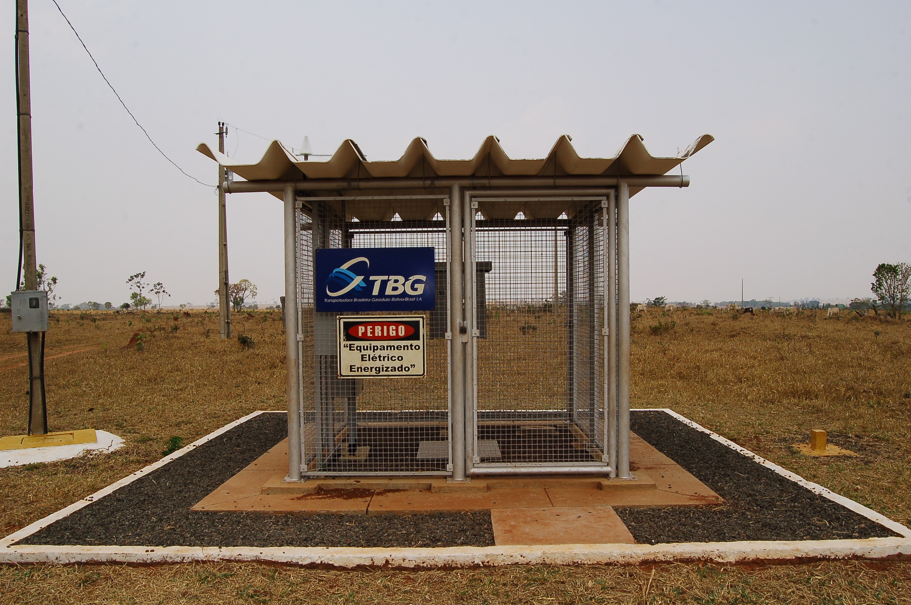
The buried segments of the Bolivia-Brazil gas pipeline are protected against external corrosion by high performance coatings (coal-tar enamel, fusion-bonded epoxy and triple-layer polyethylene), supplemented by an impressed current cathodic protection system.
Current injection on the GASBOL pipeline is done by DC current sources (rectifiers), installed throughout the pipeline, at a total of 41 sites. Proper functioning of the sources is of fundamental importance in preventing failures caused by external corrosion.
During 2003, TBG tested two prototypes of a monitoring system. It basically consists of a remote to collect the information, a satellite phone for communication and a supervisory system to display the information and store historical data. The experience was used in the draft project of the future Rectifier Monitoring System.
The basic project involved the use of remote programmable logic controllers (PLCs) for data collection and satellite communication originated by both the Control and Supervision Center and the remote (peer to peer). Power supply would be provided by the rectifiers. System autonomy should be 30 minutes in case of power failure. Thirty-nine remotes should be installed in the rectifier shelters and two should be mounted on poles. Estimated time for implementation was 11 months. The basic scope of the project is shown in Table 1.
Table 1: Basic scope of the project.
Monitor the following points:
1. Analog:
- Rectifiers input and output voltage;
- Rectifiers output current;
- Pipe Soil potential; and
- Internal panel temperature.
2. Digital:
- Shelter door, rectifier door and PLC door;
- Status of circuit breaker rectifier feeding, UPS feeding circuit breaker status and input and output fuses; and
- Count outbreaks.
3. Calculate:
- Hours count;
- Resistance of the bed of anodes; and
- Reliability of previous day, month and previous month.
4. Communication modes between the supervisory system and the remote:
- CYCLIC (Polling)–Automatic requests from the Central Control in configurable time periods;
- MANUAL–Configurable requests from the Central Control, independently for each PLC;
- EXCEPTION–For any abnormal situation and/or variation of values, the PLC should automatically call the Central Control for sending reports by exception; and
- DEMAND–At any time, regardless of the scanning cycle, allow for any PLC to be called from the Central Control.
5. Moreover, the following items were also included:
- Supply of a data server that has been embedded in the SCADA System of TBG;
- Inclusion of tracked items in the Historical Data Server Database of the SCADA System;
- Factory Acceptance Tests and Field Acceptance Tests; and
- Training and Assisted Operations.
Project Implementation
The monitoring system was mounted on three separate panels. The first panel shelters the remote, the battery charger and the satellite phone; the second panel shelters the transducers and surge suppressor protectors; and the third panel shelters the batteries.
During the detailed project development, a replacement of the UPS with 30 minutes autonomy was suggested and achieved by providing a supply system using a charger and batteries that provide autonomy of five days.
The execution of the project occurred in a satisfactory way. Some points deserved a special mention. Among them, we can mention the tests, the communications and the logistics for system assembly, often hampered by access restrictions to the rectifiers.
To avoid the occurrence of a manufacturing defect during field tests which would burden the logistics given the distances involved, all the system components were factory-acceptance tested to find flaws or discrepancies in relation to the system specification.
Requirements related to the minimum distance between antennas of the communications devices forced the factory-acceptance tests to be moved from the contractor’s facilities to one of TBG’s compressor station plants. The devices were too close to each other.
Assembly took four months and was simultaneously performed on three different work fronts.
Companies that had experience in working in cathodic protection were hired to perform the services. When the contractor started assembling the first remote, logistic difficulties showed up. Therefore, pre-assembled kits were sent to the field to make installation easier and ensure project completion as planned.
After each assembly was completed, local tests were conducted, monitoring the variables and testing the communication with the Central Supervisory in accordance with TBG’s test procedures. Once all the remotes were installed and tested, the upgrade of the SCADA system was performed so that monitoring would be done by the controller.
TBG already had a gas pipeline supervisory system. Therefore, a new real-time data server was installed for data acquisition and communication with the remotes in the field. The screens for monitoring the new system were developed in a separate environment from the main system and incorporated after being field-tested.
[inline:Supervision and Control Center.jpg=Supervision and Control Center. Photo:TBG/Renata Xavier]
There is a main screen, a communication screen, and individual rectifier screens. The operator can check all rectifiers on the main screens. A green rectifier icon means it is working properly without alarms. A red color indicates it is working outside operation specifications.
On the communication screen it is possible to view the status of communications with each rectifier, the timestamp of the last connection with the rectifier, and the remote’s phone number. Furthermore, it is possible to send commands to communicate with the remote, select the rectifiers in the polling and enable or disable the communication by exception from the remote.
The rectifier screen shows input voltage, output voltage and current values, hours of operation, resistance value (calculated) and reliability value (calculated) for the previous day, for the month and for the previous month. One can also view the CPU temperature of the remote, battery voltage and pipe-to-soil potential. A green color indicates a variable is within normal operational parameters and a red color represents a variable outside normal parameters.
All analog variables are shown on the “instrument details” screen. That screen indicates the variable TAGs and description, the variable value in engineering units and raw value (where appropriate), range in engineering units and raw (when appropriate), alarm setpoint values and timestamp.
Acknowledgements
This article is adapted from a presentation – IPC08-64037 – presented at IPC 2008, 7th International Pipeline Conference held Sept. 29-Oct. 3, 2008 in Calgary, Alberta, Canada. The original paper is copyright of ASME. The authors thank Marcos Bartelloti for the information on the cathodic protection system; Pedro Leal, manager of the company responsible for implementing the project and Marcelo Nunes for encouragement and support in the execution of this work.
Authors
Paulo Lyra Borgerth Teixeira holds a bachelor of science degree in electrical engineering from the Universidade Gama Filho (1985) and completed post-graduate work in industrial automation in 2007. He has been with TBG Transportadora Brasileira Gasoduto Bolívia Brasil S.A. since March 2002 and serves as an automation consultant responsible for maintaining the SCADA system to allow remote operation of TBG’s gas pipeline and for developing new projects related to the SCADA system.
Stella de Araujo Hasselmann holds a bachelor’s degree in chemical engineering from the Universidade Federal do Rio de Janeiro (1990) and completed an extension course in polymers at the same university in 1992. She works as a gas pipeline engineer in automation coordination for TBG and is responsible for the implementation of new systems. She has more than six years of experience in projecting, planning, testing, starting up and implementing automation and instrumentation of gas pipelines.

Comments