
September 2009 Vol. 236 No. 9
Features
Compressor Surge Control: Design And Modeling For Performance Verification
When a compressor reaches its surge condition, it loses the ability to maintain peak head and the entire system becomes unstable.
Surge is most accurately described as a system phenomenon – not a localized instability. Under normal conditions, the compressor operates to the right of the surge line. Compressor surge is sometimes viewed as a common occurrence but design of a proper surge control system should be regarded as both a necessary design practice and an effective risk-mitigation measure.
The surge-control system is an important element in the compressor system because it protects the compressor from surge over the range of compressor operations. Protection of the compressor through the surge-control system will help to avoid considerably more costly repairs or overhauls due to damaging surge conditions. Control systems may be implemented using a variety of methods and philosophies. However, the primary objective of any surge-control system should be to predict and prevent the occurrence of surge so as to reduce possible damage to the compressor and ensure a safe working environment for all station personnel. In order to ensure the system is designed properly for its various and often competing requirements, operators will choose to verify component selection, response time and behavior through a dynamic compressor surge model.
The principle of a centrifugal compressor surge-control system is based on ensuring that the flow through the compressor is not reduced below a minimum flow limit at a specific head. The majority of surge-control techniques restrict the operation of the compressor to flow rates above a defined surge-control line based on the surge margin for a particular compressor. Restriction of the operating window of the compressor in order to avoid surge because of mistakes in the surge control system design should be avoided. A properly designed surge-control system can allow the operational range of the compressor to be extended based on the response of the surge-control system.
At a minimum, the control system should actively measure the compressor head and flow through the compressor system controls and determine the resulting operating point. The recycle valve should be opened in a specified time to a valve set point determined by the control system. This signal to the valve is based on the compressor operation, its proximity and its movement (rate) relevant to the surge-control line. Opening of the recycle valve in the surge-control system effectively avoids surge by providing more flow and reducing compressor head, to move the compressor away from its surge point. In Figure 1, the compressor rundown behavior is plotted over a head vs. flow map. The compressor flow begins to drop from 900 cfm to 500 cfm. Shortly before reaching the measured surge line, the recycle valve opens and the flow through the compressor increases, to effectively avoid reducing the flow further to the left of the surge line.

A surge-control system should be capable of monitoring the operation of the compressor continuously. The function of the surge-control system is to detect the approach to surge and provide more flow to the compressor through opening the recycle valve to avoid the potentially damaging flow reversal period and surge cycling. The surge-control system should be designed for the three surge environments (which may have competing demands) and the compressor operating parameters as well as manufacturer specifications.
Various design philosophies are also provided through the use of surge-control system design criteria, which allow the performance of the surge-control system to be evaluated. The actual choice of design philosophy rests with the operating company and compressor manufacturer – and may be based on experience with a particular compressor or station. Common surge-system design philosophies may include:
- Design To Avoid Surge: The philosophy requires control system design criterion based on a calculated allowable discharge system volume. The allowable discharge piping volume should be determined by simple or more complex transient models of the compressor system.
- Design To Permit Surge Under Specified Conditions: The design philosophy acknowledges that due to operational changes to the compressor station or cost-based decisions, the compressor may not be fully protected by the existing surge-control system.
- Design Based On Risk Evaluation: The surge-control system is evaluated against a set of risk factors developed for a particular compressor and dynamic simulation is not necessarily required because of previous modeling efforts or experience.
The design of the surge-control system is more difficult than other station-control systems because of the high speed of disturbances and dynamic nature of surge. In addition, a variety of control system responses is required, depending on whether the compressor is starting up, operating in its normal operation at a low flow period, or undergoing a sudden shutdown.
Start-up Environment: The challenge to the surge-control system in the start-up environment is to quickly bring the compressor up to design speed without overheating the discharge gas. For steam turbine or single-shaft gas turbines, the start-up period will be lengthened and cooling of the recycle gas may need to be considered. In a typical start-up mode, gas is continually recycled to bring the compressor online. Operating in continuous recycle will cause the process gas temperature to increase until new gas can be supplied from upstream. With the recycle valve fully open and the downstream check valve closed, all compression horsepower will serve as heat input to the recycled gas.
Normal Process Control: The operation of the surge-control system under normal process operation is distinctly different. The surge-control system should not limit the operational range of the compressor. A relatively flat surge line equates to higher surge sensitivity to changes in compressor head. A steeper line indicates that the compressor is more sensitive to flow-rate changes or uncertainties near the surge line. In either case, the surge-control system must provide for smooth operation of the compressor. The challenge for the surge-control system in process control is to match the transition into surge (across the surge margin), which is typically gradual during normal process control, with a gradual increase in flow through the recycle valve. This requires precision control of the valve motion. The control signal and response of the recycle valve for normal process control will differ from the shutdown environment. During normal process control operation, lower gain signals should be used for adjusting the flow by opening or closing the valve in a controlled manner.
Emergency Shutdown (ESD): In an ESD event, the compressor is suddenly shut down and driver power is removed. This operation requires distinctly different functionality from the surge-control system. Delayed shutdown or slowly decreasing speed is not possible as ESDs are intended to provide immediate shutdown of the unit due to safety considerations. The surge-control system must function quickly to open the recycle valve fully because the coastdown path is not being controlled by the station operator – only by the deceleration of the compressor based on the power train inertia and any residual power in the system. The emergency shutdown requires more demanding control-system response and may alter the surge-control system design because a single valve may not provide sufficient flow quickly enough. Additional evaluation of the system may need to be performed.
The worst-case emergency shutdown occurs when the compressor is operating at maximum head at the lowest allowable surge margin. This operating point should govern the design of the surge control system – as the maximum possible differential which must be overcome by the recycle valve flow.
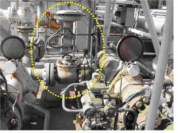
One of the most critical components in the surge system design is the recycle valve type and design (especially in high horsepower compressor installations, > 100 MMscf/d). Examples of the dramatic effects on the compressor rundown path are shown in Figure 2, for various valve capacities and delays in opening time. Note these lines are actual test results from the Southwest Research Institute closed-loop test facility on a Solar C-160 compressor. The 6-inch diameter recycle valve for the facility is shown in Figure 3. Test 7 on the performance map in Figure 2 corresponds to the normal operation of this valve.

Anti-Surge Valve Design
Complicated actuation systems on large recycle valves will introduce new dynamics into the valve actuation system that may cause a departure from linearity in the response. Response time or stroking time of the valve should not be used as the only criterion in selection of the recycle valve because this will impair the controllability of the valve and robustness of the design, needed for the process control environment.
Testing of the recycle valve for frequency response, amplitude step response in both directions (opening and closing) is recommended for valves configured with custom pneumatic systems or particularly large recycle valves (>12 inch diameter). In addition, noise attenuation characteristics and the turbulence through the valve can become major design issues for a station. High turbulence levels through a recycle valve have been shown to cause low-frequency turbulent excitation which can excite the recycle loop piping and structural support system. Recommended maximum noise level for the recycle valve is 85 dBA or less during normal operations at 1 m distance. Noise requirements for the valve during partial or full recycle may be different than those during a compressor emergency shutdown event.
Valve actuation system requirements primarily stem from the process control environment – not the shutdown environment. The key parameter to the recycle valve in the process control environment is precise control of the valve position. It is necessary to specify the speed for which the valve is allowed to change position and the amount of overshoot permitted.
In the startup environment, the key criteria is to match the valve characteristic to the compressor performance map to ensure that the compressor can come up to full speed as the recycle valve is closed. The key requirements for the recycle valve in an ESD are response time and flow-rate capacity for the given discharge system volume. For an emergency shutdown, the valve opening time is critical. Typically for the first one-second period after shutdown, the compressor deceleration will reduce the speed by approximately 30% and the head by 50 %. This deceleration period can take as long as five seconds, depending on the machine. To maintain flow through the compressor, the recycle valve must begin to open within the first second after the downstream check valve is closed.
The competing requirements for the recycle valve make use of multiple valve systems appealing. This approach to surge-control system design is not often the most cost-effective solution. In addition, the use of multiple valves for each surge-control function will require additional testing to ensure that the transition into and out of each operation is smooth.
Surge Control System Modeling
A surge model can be used to effectively design the surge-control system based on the particular compressor system. Once the system-design criteria have been established, the surge model should be used to verify the design criteria have been met. The modeling process and interpretation of results should consider the high uncertainty associated with any numerical transient model and the assumptions governing the compressor surge model. If the transient model predicts the compressor operation to narrowly avoid the actual surge condition, the high uncertainty of the model results should indicate that surge is possible. In this case, the modeling effort would suggest that the surge-control system or downstream piping volume should be redesigned.
Modeling the surge-control system in the startup, process control and shutdown environment is recommended. The shutdown case will produce the most stringent requirements for limiting piping volume and maintaining fast recycle valve response. A basic fixed volume model can be implemented to determine surge-control system dynamic response in the shutdown environment – as shown in Figure 4.

A more complex dynamic model may also be needed to model more complicated systems with multiple recycle loops or more than one compressor unit. Several basic empirical rules are sometimes used to determine if the surge-control system adequately protects the compressor. These empirical rules are not necessarily physics-based and only apply to a limited number of compressors and types of systems. A basic fixed-volume model can be used in a spreadsheet-based application to determine a more accurate system-specific discharge volume.
For more sophisticated systems and complicated piping geometries, transient (dynamic) models may be warranted. Dynamic models of the compressor surge system are distinctly different from a steady state model. The dynamic model is a purely transient study. The model will predict pressure and flow rate based on the mass accumulation in the system because these effects are transient processes. Dynamic models will predict intermediate process conditions when the flow through the compressor is changed. These are useful in the design of the compressor anti-surge control for all three working environments.
If properly modeled, the dynamic model should provide a resource for the operating company and manufacturer in protecting the compressor prior to the installation of the surge control system. An example of the amount of detail and component specifications to these models is shown in the basic 1-D Stoner model layout for the SwRI closed loop natural gas facility in Figure 5. In performing the recent testing of the Solar C-160 compressor, the authors determined the sensitivity of the modeling software to changes in valve geometry, piping selection, friction factor, and compressor deceleration curves. In addition, several non-dimensional parameters were developed to compare different compressor piping systems in terms of deceleration, system energy and bleed volume. 1 This work was published recently at the ASME Turbo Expo by J. Moore et al.

The dynamic model can also be a valuable tool in the design of a new compressor system installation. Results from the transient analysis should be used to evaluate the system piping design, placement of the downstream check valve and anti-surge valve, and the valve selection. The study should confirm the safe design of the surge-control system to adequately protect the compressor from surge. A transient simulation of the surge-control system can be used to save time and expense in changing the system after installation. The transient modeling process should be employed in the design stage of a compressor installation and adapted to suit the range of application needed. Many references in industry are available to provide examples on the use of dynamic modeling to optimize or predict the behavior of a surge-control system.
Acknowledgement
The authors would like to thank the Gas Machinery Research Council for the funding and support given to the compressor surge control research program.
The Authors
Dr. Klaus Brun, a Manager at Southwest Research Institute in San Antonio, TX, holds a B.S. from the University of Florida and an M.S. and Ph.D. from the University of Virginia. klaus.brun@swri.org.
Dr. Jeffrey Moore, a Program Manager at Southwest Research Institute in San Antonio, TX, holds a B.S., M.S., and Ph.D. in Mechanical Engineering from Texas A&M University. jeff.moore@swri.org.
Marybeth Nored, a Group Leader at Southwest Research Institute in San Antonio, TX, holds a B.S. from the University of Texas-Austin and an M.S. degree from Georgia Tech University. 210-522-3905, marybeth.nored@swri.org.
Augusto Garcia-Hernandez, a Research Engineer at Southwest Research Institute in San Antonio, TX, holds a B.S. from Universidad Central de Venezuela and an M. S. from the University of Tulsa. augusto.garciahernandez@swri.org.
Reference
1. J. Moore, R. Kurz, A. Garcia-Hernandez and K. Brun, “Experimental Evaluation of the Transient Behavior of a Compressor Station During Emergency Shutdowns,” ASME Turbo Expo paper no. 2009-59064.

Comments