
November 2019, Vol. 246, No. 11
Features
Our World Is Moving – And So Are The Pipelines
By Rhett Dotson, Pipeline Systems Consultant, and Andy Young, Geo-Hazards Engineer, ROSEN
Strain assessments and pipeline movement assessments allow operators to identify and mitigate threats presented by geohazards.
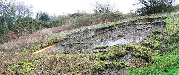
Landslides, seismic events, settlement, and erosion are some of the many examples of geotechnical hazards that can impact buried pipelines. Geohazards often result in significant external loads or loss of support, which bends the pipeline and shifts it from its original position. Significant external bending loads and the associated high strains can pose an integrity threat to the pipeline, as it may rupture or buckle.
For this reason, the monitoring of external loads through strain assessments and pipeline movement assessments is crucial to the safe operation of a pipeline. Bending strain assessments can identify areas where the pipeline is deformed beyond allowable code limits.
Pipeline movement assessments can use repeat inertial measuring unit runs and geo-spatial data to identify areas of active bending movement, making it possible to calculate a rate of change in bending strain. This article outlines how bending strain assessments can be used to manage pipelines affected by ground movement.
A 2017 validation case illustrates how these assessments provided an operator with the information needed to identify and mitigate a potentially serious loading problem.
The data for bending strain or pipeline movement assessments is captured using an inertial measurement unit (IMU). IMU technologies are often paired with magnetic flux leakage (MFL) or caliper technologies on combo in-line inspection (ILI) tools. While IMU is most often used to locate the pipeline and provide GPS coordinates, a true strength of this technology lies in its ability to quantify bending strains and pipeline movement.
The method works by detecting curvature in the pipeline, which is simply the change in angle of the pipe centerline with distance. The curvature associated with formed bends is readily identified by its characteristic profile. Any remaining curvature that is measured is assumed to have been imposed on the pipeline.
The majority of this curvature will result from the construction and installation of the pipeline, typically as the pipeline follows the contours of the ground. However, the other source of imposed curvature is from external loading effects such as ground movement and therefore is of great interest to operators for integrity management programs.
Clearly it helps an operator to know that active loading is taking place on a pipeline in advance of the development of damage. This enables decisions to be made on what mitigation should be applied and when.
There are three levels of assessment that can be applied to bending strain data:
- The locations of bending strain above a threshold level are reported and plotted.
- The strain acceptability is assessed, and the source of strain is evaluated for active movement.
- Locations of active movement are assessed in detail to develop a monitoring and mitigation plan.
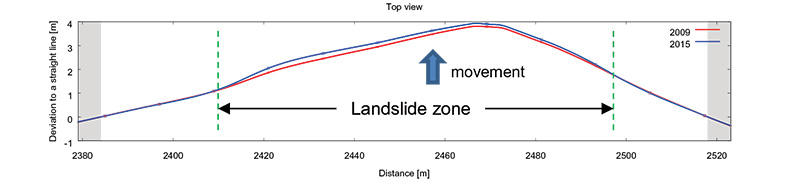
If data is available from multiple tool runs, then it is also possible to perform an evaluation of pipeline movement within the Level 1 assessment. This provides more certainty in the identification of active geohazards causing pipelines to displace. Figure 2 shows a plan view of a pipeline within a landslide. The pipe centerline has clearly displaced under the action of the ground movement between the two inspections.
The Level 2 process to evaluate the strain acceptability can take account of the pipeline condition including the presence of metal loss in the bending strain area detected by the MFL tool or geometric features identified from a caliper inspection. The severity of the strain or nature of the strain source is linked to a prioritization process and a set of recommended actions that are appropriate to the situation.
Where active movement is identified, a Level 3 assessment may be recommended. This involves structural calculations of the ground movement effects on the pipeline to provide a full evaluation of the pipeline structural integrity and predictions of the future condition with continued movement.
The analysis is integrated with IMU data of the pipeline centerline geometry and strain changes in order to develop a robust representation of the actual mechanism at site. The outcome provides a framework for decisions to protect the pipeline from further adverse loading.
Almost all operators request GPS coordinates for their tool runs, however, many operators do not take advantage of post-ILI bending strain calculations. Fortunately, once the data from an IMU is collected, it can be used at a later time (even years after the initial run) to perform a bending strain assessment.
This was the case in late 2017 with an operator in the US who completed an inspection in 2015 using a combo-ILI tool. After experiencing a product release associated with settlement related issues, the operator decided to perform a bending strain assessment on the available IMU data.
The assessment identified that high bending strains were present in the area where the failure subsequently took place. In addition, the bending strain analysis identified an additional location on the pipeline where high strains had been reported.
The operator was able to take decisive action to address the possibility of another failure based on the results of the bending strain analysis. The area of high strain was excavated, and the section of pipeline was cut-out and replaced.
As part of the pipeline rehabilitation project, the operator requested that ROSEN collect in-situ strain measurements for comparison with the reported bending strains. This data was used to verify the accuracy of the data and the bending strain assessment process. The in-situ strain was measured using strain gages placed on the pipe near the locations where the pipeline was cut.
The company provided data-collection support prior to and during the excavation stage. Prior to the main excavation for the pipeline cut-out, the site was evaluated to identify suitable locations for the monitoring exercise. This involved an appraisal of the site conditions and the bending strain data.
Installation of the strain gages requires small excavations to expose the pipe surface. However, this proved to be particularly challenging because the bending strain area was located below a business driveway that crossed an area of swamp land.
The location may partially explain the loading on the pipeline because swamp land is formed from low strength soils and these can displace under surface loads such as the construction of new roadways and earthworks.
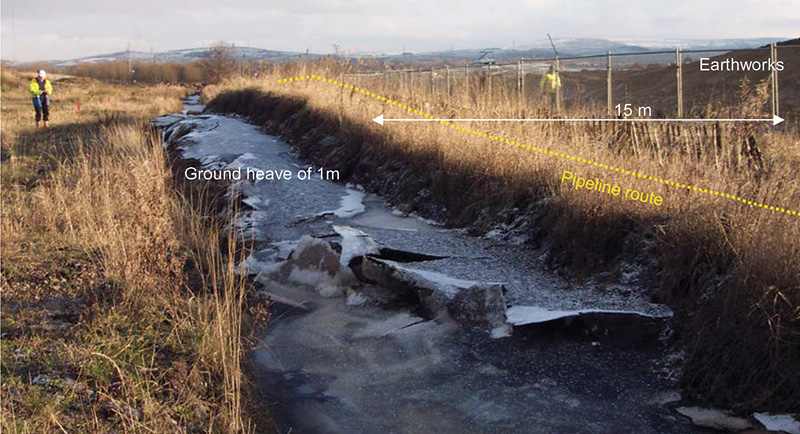
Sometimes the effects can be felt many meters away from where the surface loading is located. In the example (Figure 3), ground heave has developed on a pipeline right-of-way in very soft ground 49 feet (15 meters) away from recently constructed earthworks. The heave occurred as a direct result of the surface loading.
It is desirable to excavate as little as possible prior to the placement of strain gages to avoid relieving any in-place strain. However, equipment access and personnel safety must be considered when selecting the location for gage installation.
ROSEN’s input into selecting the initial excavation location was critical in ensuring that quality data was gathered, and the company provided on-site support and advice throughout the full instrumentation and data collection exercise including the installation of the strain gages.
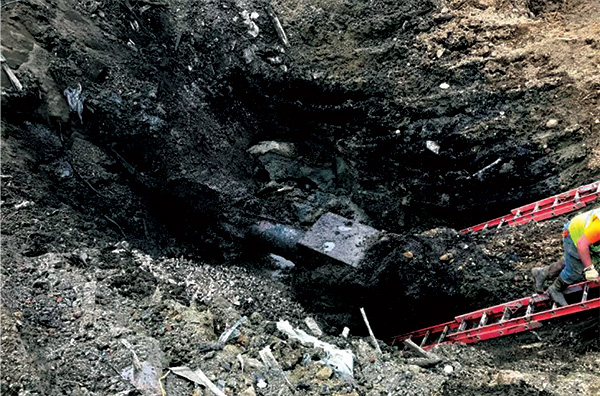
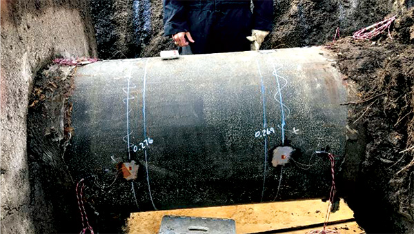
This involved correlating the in-field pipeline alignment with the profile of measured bending strains. Figure 4 shows a photograph of the excavation area once the pipe was uncovered.
The location of the final cut was selected based on the distribution of bending strains along the pipeline. Figure 6 shows a photograph of the pipes immediately after the cutting was complete. The pipe experienced significant movement after the cut, confirming the presence of external loads.
The collected strain gage data was processed to provide comparisons with the bending strain data that had been recorded by the IMU inspection during 2015.
Figure 7 shows an image reconciling the field observations with the strain gage placement and IMU bending strain data. The bending strain calculations indicated a total bending strain of approximately 1,000 microstrain (0.1%) was present in the pipeline two years before the field works.
The data gathered from the strain gages attached to the pipeline indicated a total strain of 800 microstrain (0.08%) was present prior to the cut-out. The difference between the measured strains is attributed to some stress relief occurring during excavation prior to the placement of the gages.
Nevertheless, the measured strains are within the reported accuracy of 0.02% for the bending strain calculations, confirming the excellent performance of the IMU tool.
This data provided valuable confirmation to the client regarding the performance of the IMU technology and the bending strain data. It justified the decisions made on the basis of the IMU data and provided confidence in the use of this data.
Conclusion
The assessment of bending strains in pipelines from IMU inspection tools provides a valuable and effective method to identify, evaluate and monitor the presence of geo-hazards that affect pipelines. Capturing the early development of active movement will reduce the likelihood of pipeline failure and provides more options to address and mitigate the loading threat.
Three levels of assessment can be applied to bending strain data for geohazard problems containing increasingly detailed evaluation as active loading is confirmed. The first level involves detection and listing of bending strain areas. In Level 2, the acceptability and cause of the bending strains are evaluated together with recommended actions as appropriate. A level 3 analysis involves a detailed analysis of the pipeline integrity from the ground movement and development of a framework for monitoring and mitigation.


Authors: Rhett Dotson has worked for 13 years as a consultant in the oil and gas industry. He is a graduate of Texas A&M University and is a registered professional engineer in Texas, Wyoming, and Oklahoma.
Andy Young is a principal geo-hazards engineer in Rosen’s integrity solutions team.

Comments