
March 2019, Vol. 246, No. 3
Features
Damage Tolerance Testing of Small-Diameter Pipelines
Internal and external corrosion, as well as third-party damage such as dents and gouges, are the main causes of pipeline failures worldwide. When such damage is detected by direct inspection, or in-line inspection methods, a decision to replace, repair, or accept and monitor must be made.
Over the past few decades, extensive experimental, analytical and numerical work has been undertaken to assess the severity of the different damage types and to quantify their impact on pipeline design and remaining life. This work has resulted in the development of methods such as ASME B31G, modified ASME B31G and DNVGL-RP-F101 for assessing the remaining strength of corrosion damage, the NG-18 equation for assessing the remaining strength of a gouge defect, and the empirical limits that are recommended by EPRG for assessing dent damage.
However, these methods, and the specified limits, have all been validated by mid-and full-scale tests undertaken on pipe greater than 6-inch (150-mm) nominal diameter. There are currently no methods for assessing the severity of damage to small diameter, sub 6'' nominal diameter, pipelines and pipework.
Small diameter (sub-6-inch), thick-walled pipelines and pipework, located, for example, at above ground installations, compressor and pressure reduction stations are very common. However, use of these methods or experimentally derived limits, may not be appropriate when assessing corrosion, gouge or dent damage associated with small diameter pipelines and pipework.
Experimental Campaign
During 2005 and 2007, DNV GL led a research program that was jointly funded by National Grid and BG Group (note: BG Group was acquired by Shell Global Solutions International BV in February 2016).
The aim of the research was to undertake a series of full-scale tests on pipe with (1) corrosion damage, (2) gouge damage and (3) dent damage, and to undertake an assessment of each test using the industry standard methods, as reviewed and recommended by PDAM1, toward understanding the limitations of each method and potentially extending the range of application of each method to pipe sizes below 6-inch. This would support cost-saving efforts in the pipeline industry by safely and efficiently reducing the number of unnecessary repairs.
All testing was undertaken at DNV GL’s Spadeadam Research and Testing facility located in the North of England, U.K.
Since undertaking this research, DNV GL has used the data to support development of pipeline damage screening criteria for two onshore operators; one in the Middle East, and one in the southern hemisphere. In addition, DNV GL has used the data to verify the performance of the modified ASME B31G criterion for the assessment of corrosion damage affecting 4-inch diameter topside pipework, supporting the client with development of a corrosion management procedure for the asset.
Corrosion Damage
ASME B31G2, modified ASME B31G3,4 and DNVGL-RP-F1015 are methods that are commonly used in the pipeline industry to assess the remaining strength of a pipe with corrosion damage.
The ASME B31G failure equation was validated against 47 full-scale burst tests of corroded pipe of diameter ranging from 16 to 30 inches. The modified ASME B31G method was validated against 86 full-scale burst tests of corroded pipe of diameter ranging from 16 to 30 inches. This included the 47 tests used to validate the ASME B31G method. The tests were undertaken on “vintage” pipe of relatively low toughness.
DNVGL-RP-F101 was validated against 131 tests; 79 full-scale pipe burst tests and 52 ring expansion tests, on ‘modern’ high toughness line pipe with corrosion defects. The tests were undertaken on pipe ranging in diameter from 8 to 36 inches.
In the DNV GL burst test programme, six pipe sizes were selected for testing, covering a range of pipe sizes from ½- to 6-inch nominal diameter (D/t ranging from 4.2 to 16.2). The aim was to determine whether ASME B31G, modified ASME B31G and DNVGL-RP-F101 could be used to safely assess the remaining strength of corrosion damage affecting small-diameter pipe.
In total, 80 full-scale burst tests were undertaken on pipe with machined metal loss defects, of depth 40%, 60% and 80% of the pipe wall thickness, and length of 25, 75 and 150 mm. The test program included tensile tests to confirm the actual yield and tensile strength of each pipe tested.
Prior to testing, each test pipe was subjected to detailed metrology to determine the maximum depth of the machined section and the minimum remaining ligament thickness. The measurements were undertaken at four equally-spaced positions around the pipe circumference and at either end of the machined section to determine the variation in remaining ligament thickness measurement. The exception to this procedure was the ½-inch nominal-diameter pipe samples. Due to their small size, the depth of the machined section and remaining ligament thickness was determined using a Vernier calliper to measure the circumferential variation in pipe wall thickness at either end of the pipe, and a micrometer was used to measure the reduction in diameter.
The results of the tests are summarized in Figure 1, which compares the actual failure pressure with the predicted failure pressure using ASME B31G, modified ASME B31G and DNVGL-RP-F101. Also provided is an image of the full-scale test arrangement. (Figure 1)
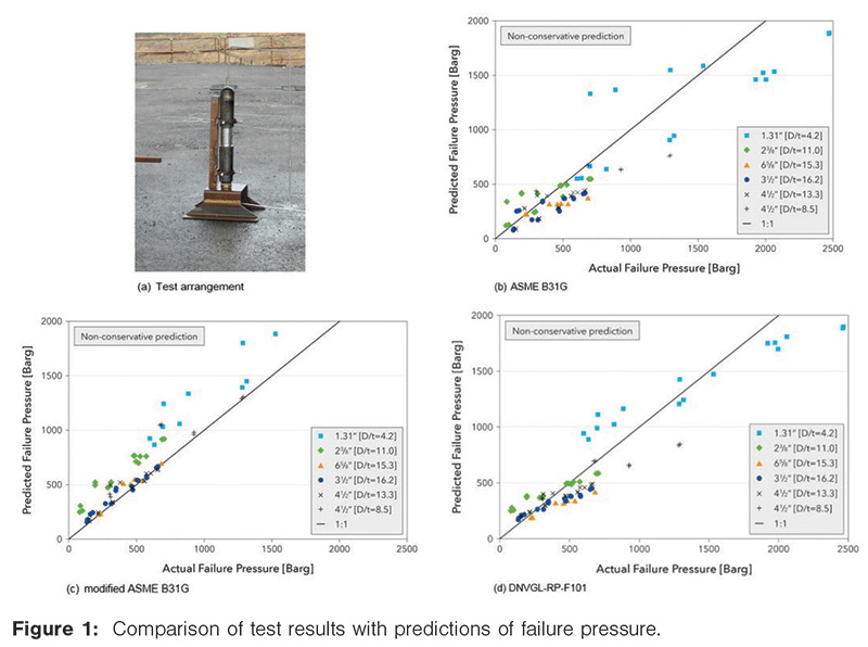
The ASME B31G and modified ASME B31G methods are limited to defects up to 80% of the pipe wall thickness in depth, d/t ≤ 80%. Some of the pipe defects tested marginally exceed this limit: the maximum being d/t = 83% (note, the limit for the DNVGL-RP-F101 method is d/t ≤ 85%). Despite this, all defects were assessed.
Overall, the key observations of the full-scale pipe burst tests and corresponding predictions of failure pressure using ASME B31G, modified ASME B31G and DNVGL-RP-F101, show that:
- ASME B31G
- Approximately 25% of the predicted failure pressures were non-conservative.
- The predicted failure pressures were within a 60% over-prediction (non-conservative), 45% under-prediction (conservative), with respect to the actual test failure pressures.
- Approximately 15% of the test results were accurately predicted.
- Modified ASME B31G
- Approximately 30% of the predicted failure pressures were non-conservative.
- The predicted failure pressures were within a 50% over-prediction, 35% under-prediction, with respect to the actual test failure pressures.
- Approximately 30% of the test results were accurately predicted.
- DNVGL-RP-F101
- Most of the predicted failure pressures were non-conservative.
- The predicted failure pressures were within a 50% over-prediction, with respect to the actual test failure pressures.
- Approximately 50% of the test results were accurately predicted.
The results suggest that ASME B31G and modified ASME B31G can be used, but only for corrosion up to 60% of the pipe wall thickness in depth. However, if the assessment is based on ASME B31G, the corresponding prediction of failure pressure can be up to 45% lower than the actual failure pressure. Although slightly better, if based on modified ASME B31G, the prediction can be up to 35% lower than the actual failure pressure.
Of the three methods, the DNVGL-RP-F101 method resulted in the greatest number of accurate predictions. However, most of the predictions were non-conservative. Even if the DNVGL-RP-F101 method was limited to d/t not greater than 60%, the failure pressure is likely to still be over-predicted (non-conservative), by as much as 50%.
In summary, the assessment methods should not be used to assess corrosion damage associated with small diameter (sub-6-inch, nominal-diameter) pipelines and pipework, without additional limitations being imposed on their use. DNV GL has supported clients by using the results from the full-scale tests to develop practical limits, enabling the safe assessment of corroded small-diameter pipelines and pipework subjected to static internal pressure loading.
Gouge Damage
The behaviour of a gouge in a pipe has been studied experimentally by a number of organisations over the years, but most notably by Battelle6,7 and British Gas.8 Both concluded that failure stress is governed by the flow stress of the material, the size of the defect, and the degree of bulging in the defect, when the pipe is subject to internal pressure. A flow stress dependent failure criterion was developed which relates these parameters.
Following a review of published methods, PDAM recommended use of this criterion, which is often referred to as the NG-18 equation.
The NG-18 equation was originally validated against the results of 47 full-scale burst tests of vessels containing artificial, machined part-wall defects and gouges, which included some tests on materials other than line pipe steel. PDAM identified an additional 45 full-scale burst test results to further authenticate the performance of the failure equation. The tests were undertaken on pipe ranging in diameter from 4 to 56 inches.
In the DNV GL burst test programme, two pipe sizes were selected for testing. The aim was to extend the range of application of the failure criterion down to 2-inch nominal-diameter pipe. In total, 24 full-scale burst tests were undertaken on pipe with machined ‘slit’ type defects; 12 tests undertaken on pipe size, 2⅜- by 5.5-mm and 12 tests undertaken on pipe size 3½- by 5.5-mm. The test program included tensile tests to confirm the actual yield and tensile strength of each pipe tested.
The test specimen geometry for each full-scale pipe burst test was similar to that shown in Figure 1(a), except the defect was an axially aligned machined ‘slit’.
Prior to testing, each test pipe was subjected to detailed metrology to determine the maximum depth of the machined section and the minimum remaining ligament thickness. The measurements were undertaken at four equally-spaced positions around the pipe circumference and at three positions along the length of the deepest section of the machined slot to determine the variation in remaining ligament thickness measurement. (Figure 2)
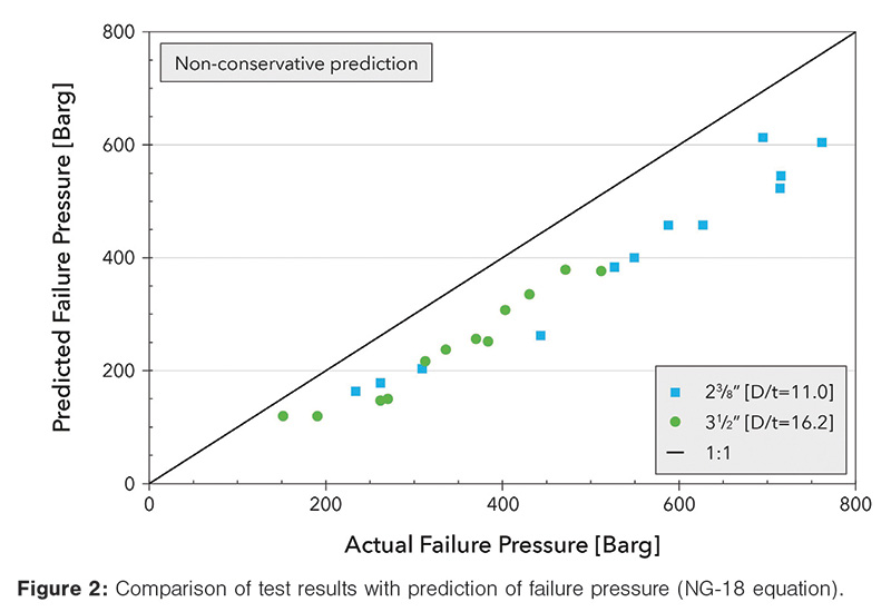
The results of the burst tests undertaken support extending the range of application of the failure equation; the criterion is valid for pipe sizes from 2-inch nominal diameter and up.
Dent Damage
There are no published analytical methods for assessing the static strength of a plain dent. The limits specified in codes and standards9,10 are empirical and based on an extensive series of tests (ring and full-scale burst tests) on pipe ranging in diameter from 6 to 36 inches.
There is no universal plain dent acceptance limit specified in the codes and standards. Limits specified are expressed as a percentage of the pipe diameter (%D), and/or an allowable strain.
In the DNV GL test programme, two pipe sizes were selected for testing. The aim was to extend the range of application of the empirical acceptance limits down to 2-inch nominal-diameter pipe. In total, 12 full-scale tests were undertaken on pipe with plain dent damage; 6 tests undertaken on pipe size, 2⅜- by 5.5-mm and 6 tests undertaken on pipe size, 3½-inch by 5.5 mm.
The plain dent limits do not differentiate between dent shape; hence three dent shapes were tested, a spherical indenter and a bar indenter (the bar dents were introduced with the indenter orientated in the pipe longitudinal and transverse directions).
The aim of the tests was to verify applicability of the client’s acceptance limit which specifies that a plain dent is acceptable if its depth is not greater than 12% D. Note, this is greater than that permitted in the codes and standards, hence, provided the tests successfully demonstrated applicability of the client’s acceptance limit, the tests would also verify applicability of the limits specified in the codes and standards.
Although the aim was to verify acceptance of a dent depth of 12% D, the target dent depth for each test pipe was 34.3% D, which includes a factor of safety of 2 on dent depth (i.e., 12% D limit x 2 is 24% D) and an allowance for spring back to account for the difference in dent depth following removal of the indenter between a pressurised pipe and an unpressurised pipe (i.e., 24% D x 1.43 is 34.3% D).
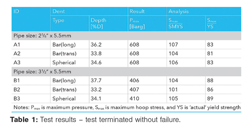
For the first six tests, the dented pipes were pressurized to a target maximum pressure. All dents survived pressurisation to a minimum equivalent hoop stress of 81% of actual yield strength (equivalent to 101% SMYS). The minimum recorded test pressure was 406 Barg. The test results are summarized in Table 1.
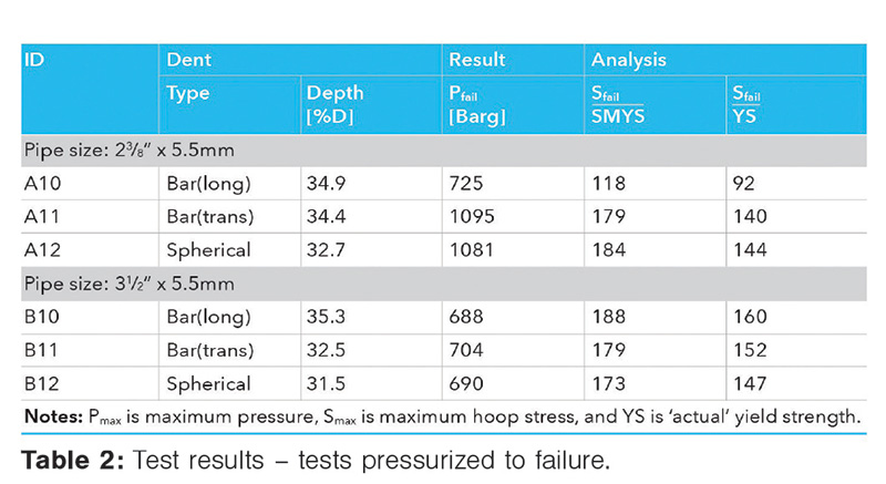
Based on the success of the first set of tests a duplicate set of test specimens was prepared. Each dented pipe was pressurized to failure. The minimum recorded failure hoop stress was 92% of actual yield strength (equivalent to 118% SMYS), and the minimum recorded failure pressure was 688 Barg. The test results are summarized in Table 2.
The results of the tests undertaken support extending the range of application of the client’s 12% D plain dent acceptance limit to 2-inch nominal-diameter pipe. As a result of these tests it is recommended that the plain dent acceptance limits given in ASME B31.89 and by EPRG10,11, which are based on a percentage of the pipe diameter, be extended to include pipework and pipelines of diameter not less than 2-inch nominal size.
Conclusions
Corrosion damage: The assessment methods, ASME B31G, modified B31G and DNVGL-RP-F101 should not be used to assess corrosion damage associated with small diameter (sub 6-inch) pipelines and pipework, without additional limitations being imposed on their use.
The results from the work undertaken were used to develop practical screening limits for both National Grid and BG Group; assessment required calculation of the pipe maximum operating hoop stress level and knowledge of corrosion depth (peak or effective) only.
Gouge Damage: The NG-18 failure equation had previously been validated using test data from pipe ranging in diameter from 4 to 56 inches. The results from the burst tests suggest that this range can be extended to include 2-inch nominal-diameter pipe.
Plain Dent Damage: The plain dent acceptance limits in ASME B31.8 and recommended by EPRG and PDAM have previously been validated using test data from pipe ranging in diameter from 6 to 36 inches. The results suggest the range of applicability can be extended to 2-inch nominal-diameter pipe. P&GJ
Acknowledgement
The permission from National Grid and Shell Global Solutions International BV to publish the experimental data is greatly appreciated.


Authors: Troy Swankie joined DNV GL in 2001, supporting the Integrity Management and Pipelines Sections in Loughborough, U.K., focusing on pipelines, pipework and pressure vessel defect/damage assessment, revalidation and life extension. He has a BEng (Hons) degree in mechanical engineering, and a PhD in materials science (mixed mode fracture mechanics).
Keith Armstrong is senior principle engineer at DNV GL and has 33 years’ experience in large-scale hazard testing and research in oil and gas related hazards. He has managed test programmes researching pipeline defect assessment, fracture propagation in pipeline materials and gas dispersion and thermal radiation hazards around pipeline releases and failures. He is a chartered mechanical engineer and member of the Institute of Engineering and Technology.
Figure 1: Comparison of test results with predictions of failure pressure.
Figure 2: Comparison of test results with prediction of failure pressure (NG-18 equation).
Table 1: Test results – test terminated without failure.
Table 2: Test results – tests pressurized to failure.

Comments