
July 2018, Vol. 245, No. 7
Features
Designing of Skin Effect Current Traced Cross-Country Pipelines
By Tittu Alagu and Koya Venkata Reddy, FACT Engineering and Design Organization, Kerala, India
Growing energy demand, coupled with the availability of sour and heavy crude, and the more conscious environmental regulations are driving refineries across the globe to enhance their facilities to process sour and heavy crude, and produce higher value middle distillates and end products.
This spurs demand for greater storage capacity for crude, as well as petroleum products handling terminals and the need for transportation of high viscous crude, high pour fuel oils and molten sulfur in liquid form. With this comes the necessity of heat tracing system.
The term heat-tracing refers to the continuous or intermittent application of heat to a pipeline or vessel in order to replace heat loss.1 Two common uses of heat tracing are preventing water pipes from freezing and maintaining fuel oil pipes at high enough temperatures that the viscosity of the fuel oil will allow easy pumping.
Industrial heat tracing are of two types: fluid- and electricity-based heat tracing systems.
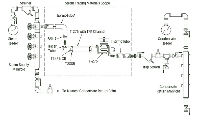
Fluid-tracing involves strapping a small 3/8 to ½-inch pipe or tube called a tracer to the pipeline or vessel to be traced and covered by thermal insulation. The tracer pipe will be supplied with a hot fluid, which transfers its heat to the main pipeline or vessel by conduction. Steam is by far the most common and preferred choice of tracing fluid used in chemical process industry for its high heat content, availability at low cost from the waste heat recovery boilers and being relatively safe compared to electric tracing.
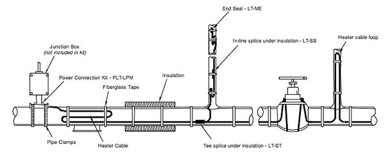
Electric-tracing involves strapping an electric heating cable to the pipeline or vessel to be traced and cover by thermal insulation. The supply of electricity to the heating cable will generate heat, which will be transferred to the main pipeline or vessel by conduction. The majority of commercial electric-tracing systems use the resistive type heater, wherein the heat is produced in proportion to the square of the current (I) and the resistance (R) of the elements (I2R). Other specialized electric tracing systems make use of impedance, induction, and skin conduction effects to generate and transfer heat.
Cross-Country Pipelines
Cross-country pipelines play a pivotal role in the effective management of the energy resources around the globe. It has been recognized as the most efficient, safe and eco-friendly mode of transportation of petroleum products and crude oil from one place to another.
Two probable scenarios in cross country pipelines in which heat tracing will be the only viable option:
- Pumping of waxy crude and high-pour petroleum products: As the waxy crude flows through a cold pipe (with a wall temperature below the cloud point of the crude) crystals of wax may be formed on the wall. As the wax thickness increases, pressure-drop across the pipe increases and the pumping pressure needs to be increased to maintain a constant flow rate. As a result, the power requirement for crude transport will increase over a period of time. Further the pipeline may require frequent flushing/pigging in order to avoid choked condition. This becomes a real setback in the case of cross country pipelines in which pumping/energy cost is relatively high, in addition to the risk of pipeline getting blocked completely.
- Pumping of molten sulfur via pipeline: Refining of crude oil and treatment of natural gas yields considerable amounts of sulfur. The extracted liquid sulfur is pelletized and transported by road vehicle, rail or water. This sulfur, on reaching its destination, has to be re-melted for further processing. The whole process incurs considerable energy cost besides, the cost of handling and storage of solid sulfur, which has its own drawbacks. And that is how pumping of molten sulfur via pipeline provided with heat tracing is considered to be economically viable alternate.
Generally, for tracing long or multiple pipe runs electric tracing is preferred over steam tracing, as steam tracing will be relatively more expensive to install and maintain. The periodic leaks and failed steam traps in a steam-traced system waste energy and demand additional labor costs for repair and replacement. Also, the electric tracing systems provide better temperature control and much more efficient utilization of energy than that of steam.
Types of Electric Tracing
Electric trace heating cable can be divided into four distinct product classifications:
- Series circuit, mineral insulated (mi) cables (constant watt output)
- Parallel circuit heating cables (constant watt output)
- Self-regulating heating cables (variable watt output)
- Skin effect heating
Each type caters to specific application and has its own advantages and disadvantages. A comparison of these electric heat tracing methods is available in the pipeline and piping book.
Skin Effect Current Tracing
Principle of operation – Skin-effect tracing system (STS)/skin-effect current tracing (SECT) is based on proximity effect, whereby heat is generated on the inner surface of a ferromagnetic heat tube that is thermally coupled (welded) to the pipe to be heat traced.
A non-magnetic conductor material (copper or aluminum) is placed inside the heat tube and connected to the tube at the far end. The tube and conductor are then connected to an AC voltage source in a series connection. When the voltage is applied in this manner, the current flows in one direction and returns through the steel tube in the opposite direction.
The full current flows in inner surface of the steel tube and in its outer surface is virtually absent. This method of heating is called skin-effect heating because the return path of the circuit current is pulled to the inner surface (approximately 1 mm) of the heat tube by both the skin and the proximity effect between the heat tube and the conductor.
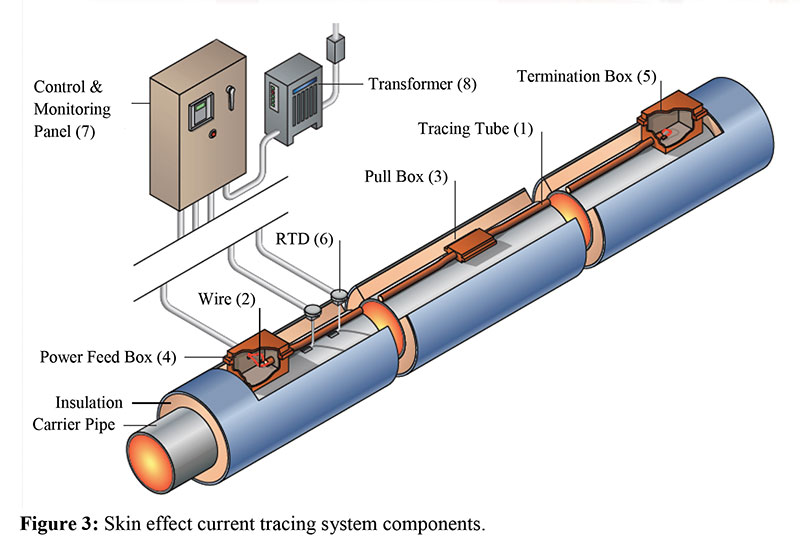
Components – The SECT system consist of the following components:
- Heat/tracing tube
- Heating cable/wire
- Pull box/splice box for cable pulling inside the tracing tube
- Power feed box for connecting the power supply
- Termination box
- Temperature sensors.
- Control panel for controlling the heating
- Custom built transformer for powering the system
Control operation – The electrical controls for the skin effect current tracing system are designed to provide the desired control of the heating system as well as provide functional indications. The system is provided with automatic and manual control modes.
The manual mode is intended for use only during start up, maintenance checks and troubleshooting of the electrical system. When using the manual control mode, care must be taken to continuously monitor the system operation. In manual mode, the temperature controller is bypassed and the system will continue to heat as long as the manual mode is maintained. The temperature indicator and alarms are active in the manual mode.
The automatic mode provides closed loop temperature control and indication. The pipe temperature sensor provides a continuous signal to the indicating temperature controller. The temperature controller compares this signal to the reference signal (set point temperature). When the pipe temperature is above the set point, the system will be “off.” When the pipe temperature is below the set point, the system will be “on.” The temperature controller has low temperature and high temperature alarm contacts.
Skin effect current tracing for pipelines – Skin effect heat tracing system is found most suitable for cross country pipe lines as per the feature listed below:
- Most economical method for extremely long pipe lengths (up to 25 km) can be traced with a single electric supply point.
- Because of the welded contact between the tube and the pipe, higher heat transfer rates are attained.
- Because of the skin and proximity effect, the outer surface of heat-producing element (heat tube) has zero potential to ground. The tube is earthed and there are no electrical potentials, which make the system safe for maintenance staff.
Applications – SECT system is widely applied in transporting crude, petroleum products and molten sulfur. Its applications also include storage tank foundation heating to prevent frost heave formation and subsea pipelines. References of application of SECT in cross-country pipelines are given below:
- 700-km, 24-inch, underground crude oil pipeline of Cairn India Limited from Mangala Processing Terminal, Barmer, Rajasthan to Salaya Terminal, Gujarat.5(2010)
- 35-km, 12-inch, above-ground dual sulfur pipeline to transfer molten sulfur from 11 producers to a sulfur pelletizer facility, Ras Laffan, Qatar5. (2009)
However the application of SECT system has its own limitations:
- Involve considerable custom design
- Do not lend easily to the production of uniform heating, and IEEE rates the method as providing only moderate system efficiency
- Installations cannot be modified, and the complete system fails with a single line break
- Skin effect heat-tracing is generally not cost-effective for pipelines shorter than 1.6 km
- Not practical for non-metallic or complex piping
Capitalized cost or life time cost of pipeline: The design of a heat traced cross-country pipeline involves calculation of the economic pipeline size. The most economical pipeline size is arrived at by comparing the lifetime cost of two or more pipeline sizes, considering the pipeline size, which provides the least lifetime cost. The lifetime cost involves computation of capitalized cost of pipeline, heat tracing system and electricity for pumping and pipeline temperature maintenance over its useful service life.
The following are the stepwise procedures to compute the lifetime cost of the pipeline:
- Choose a line size – Calculate pressure drop and ascertain the pumping power requirement
- Estimate the pipeline investment cost
- Choose a heat tracing system (skin effect current tracing)
- Calculate the maximum heat loss across the pipeline and ascertain the power requirement
- Define the no. of heat tubes required and the power feeding and distribution system
- Estimate the investment cost of the heat tracing system
- Estimate the lifetime cost of the entire system
Repeat the procedures by choosing different line sizes and compare the computed lifetime cost of all line sizes chosen to arrive at the economic pipeline size:
Surge analysis of the proposed system is to be carried out to find the maximum surge pressure developed in the system. A surge relief system shall be installed, if required to protect the pipeline or the pipeline is designed for the maximum surge pressure.
The constructability of the pipeline along the right-of-way (ROW) minimizing the obstruction/hindrance to traffic and public is planned. The above-ground or underground portions are to be clearly demarcated.
In case of power failure, the pipeline temperature tends to decrease and to avoid congealing in case of petroleum products and low temperature solidifying substances, flushing of the pipeline with a proper liquid is to be carried out. However, calculations are to be performed to see that temperature drop in the pipeline is minimal and while flushing the line average bulk temperature inside the pipeline fluid doesn’t drop below the solidification point of the mixture of the flushing fluid and original fluid in the pipeline.
The skin effect system operates as series resistance circuit having a single-phase power source. The source of power can be either from one or both ends or from middle of the pipeline depending upon the length of pipeline and effective use of power system.
Each heat tube has got the capacity to impart certain heat to the main pipe. According to the heat loss calculations, the required no of heat tubes are calculated. Total or 50% redundancy is provided for heat tubes to take care of the malfunctioning of heat tube circuit. The redundancy comes at a cost but makes the system more reliable.
The consequences of power failure and mitigation measures of it’s effects is to be clearly thought off at the time of basic design as prolonged power supply failure will defeat the purpose of heat tracing. Product solidification inside the pipeline will make the whole design intention defeated.
Other Design Aspects
- Hazardous area classification – All electric components and instruments used in the SECT system have to comply with the Hazardous Area Classification of the product being handled.
- Optical fiber-based temperature monitoring system – Provides continuous monitoring of the temperature profile of the pipeline and helps to find any cold spots. In addition, fiber-optic monitoring facilitates the measurement of average temperatures at 1-meter intervals over the length of the fiber along the entire length of the pipeline. This substantially reduces the potential effect of localized temperature variations in the pipeline. Fiber-optic temperature monitoring has particular advantages over thermister and thermocouple-based systems, as fiber-optic systems are very robust and unaffected by electrical noise.
Figure 4 shows the back-scattered light spectrum for distributed temperature measurement, a pulse laser is coupled to an optical fiber through a directional coupler.
- Current protection system – Over-current or differential current protection may be provided on the skin effect current tracing system. Over-current protection senses a current above cold starting current. If the skin effect current tracing system current rises to the set value, the system will shut down and resetting of the system is required to restart. Differential current protection senses the difference in current of two sections. If the current in one section rises over or falls below the other section, annunciation and system shut down will occur. After the cause of shut down is found and repaired, manually reset to “start” the system heating.
- Cathodic protection – Normally SECT based pipeline will have PUF insulation for heat conservation of the fluid wrapped inside the HDPE jacket for preventing any chance of water ingress and there by protects the pipe line from corrosion under insulation. Hence cathodic protection is not required for corrosion control. However, all carrier pipes and heat tubes shall be sand blasted to a surface finish of SA 2.5 and applied with high build epoxy paint of 400 microns suitable for 1,500 degree C as an additional protection to avoid corrosion. Since the pipeline systems have zero potential, skin effect heat tracing will have no effect on the cathodic protection of the adjacent lines.
References
K. Henry, Introduction to Heat Tracing, Cold Regions Research and Engineering Lab, Report no. CRREL-TD-86-1, June 1986, p. 1.
Perry’s Chemical Engineers’ Handbook, Eighth Edition, Section 10, Process Plant Piping, p. 10-135, Heat Tracing Of Piping Systems.
Fluid Heat Tracing, Steam by Chet Sandberg, P.E., Joseph T. Lonsdale, & J. Erickson, P.E., Chapter B6 Heat-Tracing Of Piping Systems, p. B.242.
Authors:

Tittu Alagu is assistant process manager working in FACT Engineering and Design Organ-isation, Cochin, Kerala, India. He has eight years experience in process engineering and has specialization in Process simulation. Tittu graduated in with a bachelor’s degree in Petrochemical Engineering from Bharathidasan University, Trichy, Tamil Nadu, India.

Koya Venkata Reddy is assistant general manager, process engineering, at FACT Engineering & Design Organization (FEDO), a division of Fertilizers and Chemicals Travancore Ltd. He has 26 years of experience in chemical plant operations. Reddy holds a bachelor’s of technology degree from Andhra University (Visakhapatnam) and a master’s of technology degree in project management from Cochin University of Science and Technology.

Comments