
June 2018, Vol. 245, No. 6
Features
Integrity Management of Unpiggable Pipelines
By Ian Murray and Inessa Yablonskikh, Baker Hughes, a GE Company
The long-term integrity of pipelines around the world is, in many cases, dependent on the ability to inspect their entire lengths using in-line inspection (ILI) technologies. When construction or location specifics prevent the use of ILI, however, managing the short-term integrity of the pipeline becomes a higher priority until it can be made piggable.
Baker Hughes, a GE company (BHGE) was tasked to review an unpiggable 10-inch offshore crude oil line, which further added to the operational complexity of the collection of condition data. Therefore, it was imperative that data collection particularly in-situ inspection (via ultrasonic scanning techniques such as auto-UT) targets the most likely locations for defects to have developed.
The solution presented here has come from a complete desktop feasibility study of the available information relating to the product and the pipeline in order to determine the likely types of internal corrosion present and the most likely locations for the corrosion to occur. The study investigated the feasibility of using auto-UT inspection to manage the short-term integrity of the pipeline and comprised of the following tasks:
- Data collection: Review of product composition and assessment of potential corrosion threats
- Pipeline configuration: Identifying the locations most susceptible to internal corrosion
- Detailed examination: Determination of the confidence in evaluating pipeline condition based on auto-UT inspection assessment of the adequacy of the existing anodes to provide the additional protection required by potential auto-UT sites on the pipeline
Data Collection
In order to determine the likely behavior of the corrosion in the line the initial step is data collection. This data was then used to make informed estimates of the corrosion mechanisms likely to be present in the pipeline.
Product Composition
The first step of the data collection phase was to understand the product, including its composition, (including but not limited to: H2S, CO-2, pH, water cut) and how the product is flowing through the line (flow rate, viscosity, solids content, etc.) to understand the potential mechanisms for internal corrosion in the line.
Further knowledge of the corrosion control measures being taken to mitigate against corrosion, such as corrosion inhibitor and the application of biocide treatments, was required, too.
Data was also collected on corrosion rates observed in the pipeline, including results from corrosion monitoring probes and coupons, as well as laboratory testing and operational observations.
Assessment of Threats
Utilising the data collected, the next step was to combine and analyse this information to understand the internal corrosion threats and growth rates, which have the potential to be present in the pipeline.
These threats included pitting and general corrosion, sour cracking (HIC and SSC), microbial corrosion, mesa corrosion and erosion corrosion.
From the review it was determined that under the current operating conditions, the principal risk of corrosion was from pitting corrosion. However, this was considered to be low as long as an effective inhibition program was ongoing and the current low water, H2S and CO-2 content were maintained. Under the current operating conditions, FeS film formation is expected to provide protection but low level corrosion activity might take place where this film is damaged.
The most serious internal corrosion threat to the pipeline is expected to occur if the operating conditions are changed in a way that leads to increase of water cut, H2S and CO-2 content or affects the durability of the protective FeS film.
Based on the review it was concluded that internal corrosion was most likely to occur where the conditions for water drop out are met.
Slope Angles, Topography
According to NACE SP-208 LP-ICDA methodology, internal corrosion threat in liquid petroleum systems is based on the assumption that corrosion only occurs when water drops out of the hydrocarbon phase and wets the steel surface of the pipe. Accumulation of water does not mean a 100% certainty for the presence of corrosion. The actual development of the corrosion process depends on the wettability of the internal pipe surface.
Locations predicted to have the highest susceptibility to water accumulation for the longest duration of time are expected to have the highest likelihood of experiencing significant internal corrosion. Such locations include (but are not limited to) low spots or places where the pipeline goes up a steep slope such that the liquid velocity is insufficient to carry the water over the next high point.
NACE SP-208 provides an approach to predict water accumulation in a pipeline based on the critical inclination angle. The pipeline inclination angle, which corresponds to a rapid drop of the in-situ water velocity, is a critical angle.
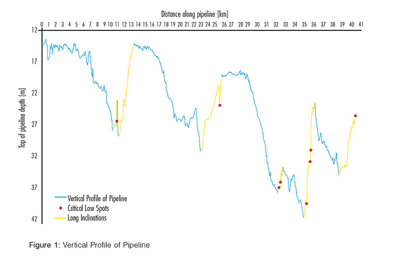
Segments of the pipeline upstream from such an incline are locations where water would be expected to accumulate and should be considered for examination. In the case of the subject pipeline the inclination angle of 2° was determined to be critical for water accumulation. The most critical low spots and inclined sections in the subject pipeline are in Figure 1.
Pipeline Fittings
Corrosion in locations, where water accumulates, may be aggravated by solids accumulation. Solids may shield the pipe wall from the action of inhibitor or biocide, as well as create a niche for micro-organisms (sulphate-reduced bacteria, etc.) to thrive (as flushing by product flow will be prevented). Progressive settling of solid materials may be associated with product turbulence effects, caused by flow disturbance from various pipeline fittings.
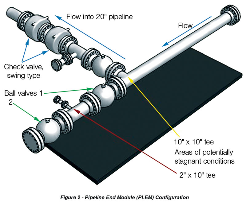
During the review, it was determined that the most likely area for this to occur in the line would be the pipeline end module (PLEM) (Figure 2). It was found that due to the configuration in this area the bottom part of the tee may be susceptible to water, solid and wax deposition and microbial accumulation.
Detailed Examination
Using the guidance in NACE SP0208, the appropriateness of using auto-UT to support the assessment of the condition of the pipeline was confirmed. As discussed previously, the potential susceptibility of the pipeline to low-level internal corrosion in the locations of low spots, upstream segments with overcritical inclination angles and in the dead-leg had been established. Based on this assessment, four sites were selected for priority UT scanning, comprising of two locations within the PLEM and two low spots in the pipeline considered to have the highest likelihood for internal corrosion initiation.

The next task was to consider other inherent risks to the pipeline before, during and after the auto-UT inspection. There are industry standard ractices for creating ultrasonic inspection sites and conducting either diver-manipulated or automatic corrosion mapping. A schematic diagram of an auto-UT site, which is normally in the region of 3 meters in length (Figure 3).
An additional consideration was the external corrosion protection of the bare pipe exposed at the auto-UT sites. It was necessary to check that the existing external corrosion anode protection was adequate to meet the extra demand of the bare pipe. It was concluded that if the auto-UT sites were to be used for a one-off survey only and the protective coating is reinstated immediately after the survey, the requirement for additional CP protection would not be applicable.
However, if the auto-UT sites are going to be used for monitoring the pipeline integrity for a period until the pipeline is made piggable (18 months-2 years), then additional anodes would be required to provide sufficient protection to the exposed pipe at the auto-UT sites.
Conclusion
Following the detailed examinations at the four selected sites, the auto-UT scans were analysed and evidence of low level, isolated internal corrosion pits were observed at one of the four sites. The low level corrosion pits were evaluated to be insignificant in severity in relation to the integrity of the pipeline and annual monitoring at the auto-UT sites was recommended to determine the rate of corrosion growth until the line can made piggable.
This case study demonstrates that, even in cases where a pipeline cannot be pigged and access to the pipe is difficult, there are industry accepted methodologies available to support pipeline integrity management. In this case, BHGE provided integrity management feasibility study to support the pipeline operator by:
- Identifying feasible corrosion threats and growth rates
- Predicting the locations of highest corrosion risk
- Recommending targeted in-field examination to evaluate pipeline condition
- Providing a fitness for purpose assessment
- Managing the integrity of unpiggable pipelines. P&GJ

Comments