
March 2016, Vol. 243, No. 3
Features
Energy Saving Along with Green CNG Decompression
A CNG decompression process, Vortex PRS-CNG, developed by Universal Vortex, Inc. (UVI), allows for complete elimination of high-pressure gas preheat and raises the pressure-regulated gas temperature without applying any external man-made energy. The technology places no limitation on CNG flow rate and the process initial and final/delivery pressures.
UVI’s technology provides a thermal solution to secure non-freeze pressure reduction of non-preheated gas. The core of the technology is the proprietary self-heating vortex pressure reducer (VPR), a device with no moving parts, used as a single CNG pressure regulator.
In the VPR, high-pressure gas expands in the unit’s static tangential nozzle down to the delivery pressure. While in the VPR’s cylindrical body, the rotating low-pressure gas undergoes energy division (vortex phenomenon), forming two currents: cold and hot. The currents coexist in the VPR and exit the unit through a single-discharge orifice.
Prior to exiting the VPR, the hottest portion of the hot flow is internally directed to warm up the unit’s inlet nozzle (proprietary self-heating provision), thus preventing the inlet depressurized flow from freezing up. The vortex cold and hot flows, recombining at the VPR discharge, negate their temperature differences. Therefore, the temperature of the combined flow at the VPR single discharge reflects only the Joule Thomson (JT) temperature drop in the expanded gas.
The gas exiting the VPR is extremely cold due to JT temperature drop in non-preheated expanded gas. The UVI process takes advantage of these low temperatures since the pressure-regulated gas now can be efficiently warmed up by heat exchanging with any low-grade medium (primarily, ambient air) performing as a “cold sink.”
Depending on the actual temperature of the now-warmed, pressure-regulated gas, it can be either instantly used or moderately post-heated to bring the gas temperature to the specified delivery temperature.
The energy required for the post heat is just a fraction of the energy required using conventional PRS pre-heating to secure its non-freeze pressure reduction and to satisfy its delivery temperature.
The process simulation illustrates the energy savings at a typical VPRS-CNG with an initial tank pressure of 3,700 psi, a delivery pressure of 75 psi, and a required delivery gas temperature of 50°F under some common ambient air temperatures.
An ambient air heat exchanger (AAHE) with thermal approach of 10°F is used to absorb cooling duty of the depressurized CNG. An average specific JT coefficient is assumed as 3.6°F per 100 psi. It is assumed that CNG temperature in the tank is equal to ambient air temperature.
Case 1: Ambient air temperature 60° F
∆T JT value in the expanding gas is 130°F. Actual gas temperature at the PR discharge (3,700 psi to 75 psi pressure differential) is 60 -130 = -70°F
Conventional process: To maintain pressure regulated gas at 50°F, the high pressure gas has to be at 180°F. Therefore, a 120°F preheat is required.
VPR: pressure-regulated gas at -70°F is directed to an AAHE with 10°F thermal approach, where the gas is warmed to 50°F. No additional post heat is needed.
Case 2: Ambient air temperature 5°F
∆T JT value in the expanding gas is 130°F. Actual gas temperature at the PR discharge (3,700 psi to 75 psi pressure differential) is 5 -130 = -125°F.
Conventional process: To maintain pressure regulated gas at 50°F the high-pressure gas has to be at 180°F. Therefore, a 175°F preheat is required.
VPR: pressure-regulated gas at -125°F is directed to an AAHE with 10°F thermal approach, where the gas is warmed to -5°F. Additional post-heat of 55°F is needed.
Case 3: Ambient air temperature is -25°F
∆T JT value in the expanded gas is 130°F. Actual gas temperature at the PR discharge (3,700 psi to 75 psi pressure differential) is -25 -130 = -155°F.
Conventional process: To maintain pressure regulated gas at 50°F the high-pressure gas has to be at 180°F. Therefore, a 205°F preheat is required.
VPR: Pressure-regulated gas at -155°F is directed to an AAHE with 10°F thermal approach, where the gas is warmed to -35°F. Additional post-heat of 85°F is needed.
VPRS Concept Design
The Vortex PRS consists of one or more VPR runs, an upstream on/off valve, a heat exchanger, buffer storage (receiver) and a fine-tune pressure regulator.
A VPR is capable of making a single non-freeze pressure cut from the initial tank pressure down to the delivery pressure. However, a large difference between gas flow rates at extreme pressures results in the need to oversize the AAHE beyond a reasonable cost/benefit ratio. To reduce the AAHE excessive size/cost, a few VPRs of different capacities are used to provide a steady decompressed gas flow under declining gas pressure.
Each VPR operates in a designated pressure range specified within a full range of the tank initial and final pressures. The number of VPR and relative sizes influence the size of the downstream ambient air-heat exchanger and buffer storage (receiver). The VPRS-CNG design generally allows 25-30% excess flow (the AAHE oversize).
Thermal Management
The VPR conducts non-freeze pressure reduction so that heating of the gas flow prior to pressure reduction is not required. Thermal conditioning after VPR provides heat to the process flow to compensate for JT cooling. For ambient air source thermal conditioning, a finned tube heat-exchanger (AAHE) with a thermal approach of 10°F is generally used.
Continuous operation frost buildup resulting from condensation is addressed by considering either multiple ambient air-heat exchangers operated in parallel with only one operational at any time, or a single ambient air-heat exchanger with a small heater used periodically to aid in defrosting.
The buffer receiver compensates for any imbalance between the VPR flow (receiver inlet flow) and the demand flow rate (receiver outlet flow). The buffer storage overcomes the limitation of the VPR’s unchangeable (no moving parts!) inlet orifice.
Since the VPR’s (single or combined) capacity will, at all times, equal or exceed the delivery flow rate, an interstage receiver is used to balance supply and demand. The gas pressure in the inter-stage receiver is raised until the receiver is at the high-pressure set point, whereupon flow is stopped and not restarted until the receiver is depleted to the low set point.
Vortex Gas Management
VPR gas management can be done manually or automated. Using input data from pressure gauges (manual) or switchers/transmitters (automated) a VGMS will control flow and manage gas pressures.
Using input data on inlet pressure and the pressure in the inter-stage storage, the on/off valves on the inlet to the VPR and the stage bypass valves will be opened and closed. In this way, the VGMS will control which VPRs are active, as well as manage the inter-stage storage pressure between minimum and maximum set points.
VPRS Case Studies
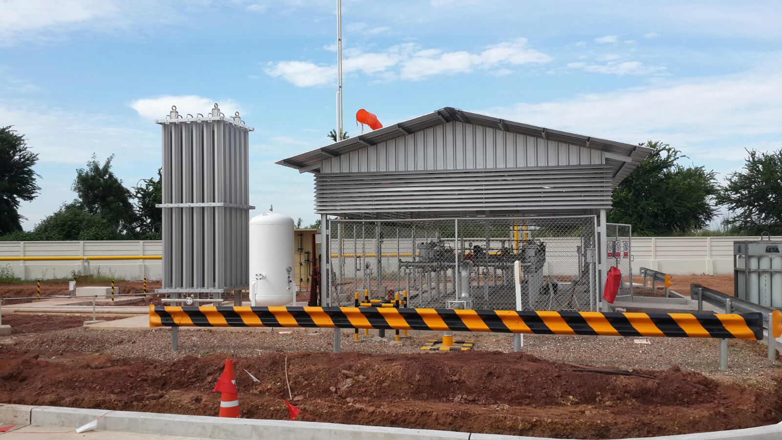
An example of a VPRS CNG design and operations is a 1,000 nm3/HR (35,000 scfh) facility in Thailand. Initial tank pressure is 250 bar, delivery pressure is 5 bar.
The VPRS-CNG configuration for the required capacity consists of three standardized VPR of different sizes. The other components are on/off solenoid valves, an air-source heat-exchanger, an inter-stage receiver accumulating pressure-reduced gas and a fine-tune pressure regulator to maintain the desirable delivery pressure and flow (Figure 1).

The control logic of the VPRS-CNG decompression provides for gradual increase of the total VPR inlet cross-section to maintain a steady delivered gas flow upon the tank pressure decrease.
This is achieved by interconnecting the available VPR in a way by which each designated tank pressure range is served by a VPR or combination of the VPR with a specified total inlet cross section area. (Example: Unit B capable to deliver 1,000 nm3/hr at 175 bar serves in a pressure range of 250 to 175 bar; Unit A capable to deliver 1,000 nm3/hr at 125 bar serves in a pressure range of 175 to 125 bar; Units A and B capable to deliver 1,000 nm3/hr at 89 bar serves in a pressure range of 125 bar to 89 bar.
The gas pressure in the interstage receiver is raised to 30 bar (high-pressure set point), whereupon flow is stopped and not started until the receiver is depleted to 6 bar (the low set point).
As the CNG tank depletes, the ratio of the VPR inlet to outlet pressure – which is the VPR driving force – declines and at the tank pressure of 45 bar the gas at the CNG tank is routed (via the AAHE) to the conventional pressure-regulating run.
Peak Shaving
Example: A number of trailer-mounted facilities are operated by Questar Gas in Utah with a non-controlled gas flow supply from CNG tank (initial pressure 3,000 psi) to gas supply network (about 60 psi).
Two VPR units are set up in parallel to provide the capacity for emptying the tank in a specified time. The pressure-regulated gas at the VPR discharge is warmed up in the AAHE.
Energy, Cost Savings
Implementation of the VPRS CNG technology instead of the conventional PRS-CNG will eliminate the need for fuel or electricity to pre-heat the natural gas prior to pressure reduction.
Further savings should result from reduced maintenance cost as ambient-heat air exchangers will require minimal maintenance – far less than a heat exchange system that consumes fuel or uses electricity.
Environmental Benefits
Commonly, CNG decompression facilities consume gas equivalent to 0.6% of the total flow as fuel to pre-heat the CNG prior to its pressure regulation. The table shows amounts of emitted carbon dioxide (CO2) at CNG decompression facilities of various capacities.
These air pollutions will be completely eliminated by a Vortex PRS-CNG.
CO2 emission, kg/HR
3,000 scfh (85 nm3/hr): 0.98
10,000 scfh (283 nm3/hr) 3.27
35,300 scfh (1,000 nm3/hr) 11.54
70,700 scfh (2,000 nm3/hr) 23.10
247,500 scfh (7,000 nm3/hr) 80.85
Technical background: The chemical equation for burning methane: CH4 +2*O2 = CO2 +2* H2O. Therefore, 1 kg-mole of CH4 corresponds to 1 kg-mole of CO2. Since 1 kg-mole of CH4 = 16 kg and 1 kg-mole of CO2 = 44kg, then 1 kg of burned CH4 generates 2.75 kg of CO2.
By Lev Tunkel and Ross Gale, Universal Vortex, Inc.

Comments