
October 2015, Vol. 242, No. 10
Features
Mitigating AC Corrosion on Cathodically Protected Pipelines
It’s becoming more common for pipelines ? even cathodically protected ones ? to experience external corrosion due to induced alternating current. This induced AC corrosion can be difficult to detect, let alone control, without an understanding of what it is and how it occurs. This article covers the fundamental concepts behind this unique type of corrosion, along with strategies for controlling it and protecting pipeline personnel from AC-related safety hazards.
Key Facts About Induced AC Corrosion
Over the last decade, corrosion experts, regulatory agencies and pipeline owners have increasingly devoted resources to understanding, detecting and controlling induced AC corrosion. Although this phenomenon is still under study, the corrosion control industry has an ever better understanding of it than in the past.
AC Coupling Plays a Major Role
It’s widely accepted that AC coupling can introduce significant safety hazards, as described in SP0177-2014, a standard originally published by the National Association of Corrosion Engineers (NACE) in 1977. What’s emerged more recently is that this same AC coupling can also contribute to AC corrosion, despite the presence of a properly designed and installed cathodic protection system. NACE describes this phenomenon in its 2010 technical committee report, AC Corrosion State-of-the-Art: Corrosion Rate, Mechanism and Mitigation Requirements.
There are three types of AC coupling: resistive, capacitive and inductive. The first two primarily introduce personnel safety hazards while the third significantly contributes to AC interference by continuously coupling AC power to an adjacent pipeline through the presence of an alternating magnetic field associated with operation of the high-voltage AC (HVAC) system.
Growing Risk
Induced AC corrosion is becoming more of a problem today due, in large part, to the frequency at which pipelines and HVAC power systems are being co-located in shared rights-of-way (ROWs). In North America, the reason for this increase in co-location begins with shale plays. As these plays generate oil and natural gas at a feverish pace, the need to build infrastructure to move product to market is intensifying.
At the same time, it is becoming increasingly difficult for operators to secure new ROWs. To avoid these difficulties, more operators are laying their pipeline adjacent to an existing power line. While this may appear to be an easy solution, it too comes with challenges. Co-locating ROWs exposes resources – both human and material – to the risks associated with AC coupling.
It Can Cause Damage
It is relatively easy for damage caused by induced AC corrosion to be misdiagnosed since it is normally characterized by localized pitting that can be attributed to a number of other factors. It can take years for a correct diagnosis to emerge and for final conclusions and recommendations to be developed. Still, there’s mounting evidence of AC-related pipeline wall loss, and even failures. Here are a few examples:
• A 2002 natural gas leak occurred due to a pinhole perforation near the center of pit that was approximately 25 mm in diameter. This defect occurred on a cathodically protected natural gas pipeline south of Oswego, NY and was ultimately attributed to induced AC corrosion [1].
• In 2001, AC corrosion was determined to have caused defects on a section of a cathodically protected 412 km, 10 inch ethylene pipeline running through Scotland and England. In one area, these defects were characterized by metal loss of up to 40%[2].
Determining Whether Assets are at Risk
Prudent operators are becoming increasingly conscious of several factors that could contribute to AC interference and related safety hazards.
Adjacent Power Systems
The presence of adjacent HVAC power transmission systems is a key indicator that AC coupling could adversely affect a pipeline. The following conditions indicate a higher likelihood of an induced AC problem:
1. Power transmission systems that operate at 69 kV or greater
2. Pipeline/AC power systems that are co-located for one mile or more
3. Pipeline/AC power systems with a lateral separation of 500 feet or less
To fully assess the risks associated with induced AC, all co-located facilities should be evaluated by a properly trained corrosion control professional.
AC Current Density
The corrosion control industry generally considers AC current density to be the most critical factor in predicting AC corrosion risk to pipelines. Current density greater than 100 A/m2 indicates a high risk of AC corrosion, while current density between 20 and 100 A/m2 indicates a medium risk, and current density less than 20 A/m2 suggests a low risk [3].
Thus, pipeline operators should consider AC current density in any AC interference analysis. They should also consider factors that contribute to AC current density such as AC pipe-to-soil (P/S) potentials, soil resistance, pipeline coating defect size, pH at the pipeline surface, and changes in pipeline or AC power system alignment.
One way to consider these contributing factors is by adding AC P/S potential testing to annual cathodic protection system evaluations. This can help identify areas where safety or personnel hazards exist. This same data, when coupled with soil resistance information, will also help identify areas of elevated AC current density with a direct correlation to the potential for AC-related corrosion.
External Corrosion Direct Assessment (ECDA) or Inline Inspection (ILI) Data
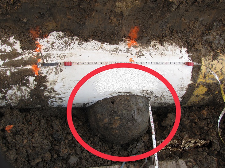
When conducting a visual inspection in conjunction with an ECDA dig, operators should look for the telltale tubercle – a hard deposit of soil and metallic corrosion product at the coating defect. This will often be associated with a distinct morphology characterizing AC corrosion (see Figures 1-2).
Additionally, ILI data indicating significant instances of external wall loss in a co-location corridor should be cause for further investigation, including an AC interference study. This wall loss data becomes more relevant if the identified locations can be correlated with other data (e.g., increased AC current density, AC pipe-to-soil potentials, soil resistance, pipeline coating defect size, pH at the pipeline surface, and changes in pipeline/AC power system alignment). New ILI tools now under development are reported to show promising results for detecting and measuring AC current flow, but accurate current measurement from within the pipeline remains elusive.
Mitigating the Effects of AC Coupling
There are two generally accepted methods of mitigating the personnel hazards and corrosion risk associated with AC coupling: field measurement and design, and theoretical modeling.
Field Measurement and Design
Field measurement and design is a multilayered approach that involves collecting field measurements and HVAC power data, with the goal of installing an AC mitigation system that protects personnel and the pipeline while allowing continuous monitoring (Figure 3). This approach is typically the most common AC mitigation strategy due to its practicality and cost-effectiveness.
Figure 3: Steps in the Field Measurement and Design Process
Step 1: Collect and Analyze Data
The first step of this approach is to research existing HVAC and pipeline data, followed by collecting actual AC potentials, soil conditions, pipeline/AC power system alignment data, and AC current densities. During this step, operators should also document all aboveground appurtenances, analyze pipeline/AC power system parallel and lateral distances, and identify potential areas of peak AC voltage.
Step 2: Design the AC Mitigation System
The second step involves combining HVAC data, pipeline data, and environmental data into a comprehensive AC mitigation design. This design must include two closely related components: protection for personnel and protection for the pipeline itself. Figure 4 shows a typical AC mitigation system that an operator might install in a co-located corridor.
Figure 4: Combining Multiple Strategies in a Typical Integrated AC Mitigation System
Protect Personnel
Strategies for designing an AC mitigation system that protects personnel from the risks associated with AC coupling include posting clear, visible warning signs wherever AC voltage may be present and choosing a dead-front CP test station to protect personnel from accidental contact.
Pipeline operators can also protect personnel through using gradient control mats (GCMs) to create a “safe zone” immediately adjacent to above-ground appurtenances (see A in Figure 4). This will reduce the risk that operating personnel will be exposed to hazardous AC voltages during both normal operation and fault conditions. Operators should take care to decouple GCMs from the pipeline to maintain effective CP and consider a separate, galvanic CP system to protect the GCM from corrosion.
Protect the Asset
The second component of designing an AC mitigation system ? protecting the asset ? most often involves some combination of using DC decoupling devices, connecting available natural drains, providing additional grounding, and installing coupon test stations.
Many times, operators can utilize existing structures, such as steel casings, to provide AC grounding. These structures, also called natural drains (see B in Figure 4), should be identified during field testing. Additional grounding options include horizontal linear-type ground systems or deep vertical-point ground (DVPG) systems (see C in Figure 4). Both of these require consideration of existing soil characteristics and ROW availability.
Carefully sized DC decoupling devices are also key to protecting pipelines from induced AC corrosion. They establish electrical connections to the various components of the AC mitigation system, allowing continuous passage of AC energy while simultaneously blocking DC current flow, thus maintaining the DC electrical isolation required for effective operation of the CP system.
Coupon test points are another key component of any AC mitigation system (see D in Figure 4). They allow for effective monitoring of both AC potentials and AC current density by providing a steel surface exposed to the surrounding soil. That steel surface is representative of coating holidays found on the pipeline under study.
Coupons should ideally be placed in areas where geometric alignment changes to co-location exist, since there will be a peak in AC voltage at the point of intersection (PI). New and better solutions for measuring AC current density via coupons are rapidly entering the marketplace, such as the Triton® coupon test station, which incorporates two DC coupons, an AC coupon, and a stationary reference electrode.
Step 3: Test and Monitor the Results
The third and final stage of the field measurement and design approach requires careful monitoring of the pipeline. This allows operators to continually monitor and adjust the mitigation system in response to HVAC operational changes that will inevitably occur or AC mitigation system damage that occurs during the course of pipeline operations.
Theoretical Modeling Design
Computer-based modeling can assist pipeline operators in developing an effective AC mitigation system. This data-driven, theoretical approach relies on available HVAC system information, measured physical dimensions of the pipeline and HVAC systems, and soil resistance data.
This information is fed into a complex software application that calculates the theoretical ground resistance required to mitigate the predicted AC voltage as well as estimating the residual AC voltage that would be present following installation of an AC mitigation system.
This approach can result in the design of an effective AC mitigation system, however, it’s relatively expensive and depends on the accuracy of available data.
Conclusion
Ever increasing instances of co-located HVAC and pipeline systems have made AC interference more of a concern than ever before. The good news is that pipeline operators can mitigate this interference through a carefully engineered and built-for-purpose AC mitigation system, protecting both their personnel and assets.
References
1. Wakelin, Robert G. and Sheldon, Christopher, Investigation and Mitigation of AC Corrosion on a 300 mm Diameter Natural Gas Pipeline.
2. Ellis, Roger, AC Induced Corrosion on Onshore Pipelines: A Case History.
3. NACE, AC Corrosion State-of-the-Art: Corrosion Rate, Mechanism, and Mitigation Requirements.
Author: Clay Brelsford, president of Bass Engineering, has over 34 years of experience designing, installing, supervising and maintaining galvanic and impressed current CP systems. A NACE Cathodic Protection Specialist and active instructor for NACE CP1 and CP2 courses, Brelsford holds a B.S. in Electrical Engineering from Texas A&M University and is a registered professional engineer in the state of Texas.
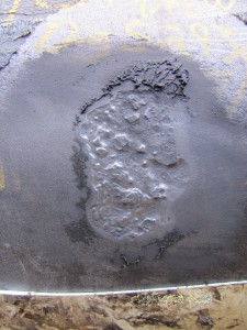
Figure 2: Metal Loss Associated with the Tubercle in Figure 1.

Figure 3: Steps in the Field Measurement and Design Process.
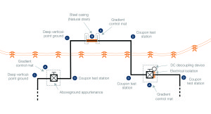
Figure 4: Combining Multiple Strategies in a Typical Integrated AC Mitigation System

Brelsford

Comments