
September 2012, Vol. 239 No. 9
Features
CO-2 Compression Research Advancing At SwRI
Coal is used to generate about half of all electricity consumed in the U.S. Unfortunately, coal contains high carbon content and produces double the CO-2 emissions when burned compared to natural gas. Because of growing concern over greenhouse gas emissions, the U.S. government and utilities are developing technologies to separate carbon dioxide both pre-and post-combustion.
In the effort to reduce the release of CO-2 greenhouse gases to the atmosphere, industry is pursuing technologies for sequestering CO-2 emitted from new power cycles including Integrated Gasification Combined Cycle (IGCC) and Oxy-Fuel, as well as from traditional Pulverized Coal (PC) power plants. Significant progress has been made in sequestration of CO-2 from power plants and other major producers of greenhouse gas emissions.
Compressing the captured CO-2 stream requires significant power, which affects plant availability, capital expenditures and operational cost. The power penalty for carbon capture can be as high as 27-37% for a traditional PC power plant and 13-17% for a typical IGCC plant. The compression represents a significant percentage of this total.
Novel Compression And Pumping Techniques
SwRI researchers, under funding from the U.S. Department of Energy National Energy Technology Laboratory and industry partners, are working to reduce this penalty by developing novel combined compression and pumping processes. The research supports reducing the energy requirements for carbon capture and sequestration in electrical power production. These technologies are also applicable to other gases including natural gas and air compression. The primary objective of this work is to boost the pressure of CO-2 from near atmospheric to pipeline pressures with the minimal amount of energy required.
Previous thermodynamic analysis identified optimum processes for pressure rise in both liquid and gaseous states. Isothermal compression is well-known to reduce the power requirements by minimizing the temperature of the gas entering downstream stages. Combined compression-liquefaction-pumping schemes also showed good promise.
Isothermal compression can be accomplished with an integrally geared machine, where multiple pinions are driven off of a common gear. However, the reliability of integrally geared compressors cannot match the in-line centrifugal machines so widely used in the oil and gas industry. To address these issues, SwRI researchers designed an internally cooled, inline centrifugal compressor diaphragm (patent pending) that removes the heat of compression without the need for external intercoolers using liquid cooling.
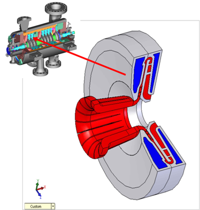
The diaphragm removes heat of compression between each impeller by passing cooling water through the diaphragm. Temperature increases, due to the work input of the impeller, are reduced through the diaphragm flow path thereby reducing the temperature into the downstream stage. To validate their predictions for both aerodynamic and heat transfer performance, SwRI researchers built and tested a single-stage prototype diaphragm.
The design, shown in figure 1, removes the heat of compression inside a multi-stage centrifugal compressor used for CO-2 compression applications.
Significant challenges exist in cooling a high-velocity gas internal to the compressor, such as limited surface area and minimizing pressure drop of the gas stream. However, using three-dimensional computational fluid dynamics, researchers developed conjugate heat transfer models that combine the diaphragm structure, cooling fluid and the diaphragm process gas flow path. Using these models, researchers achieved an optimal design that provides good heat transfer while adding no additional pressure drop. The diaphragms were designed to permit fabrication by first machining the individual components, welding the pieces together, heat treating and machining the weldment.
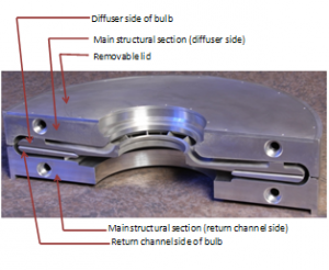
Figure 2: The compressor cooled diaphragm half shows the aerodynamic flow path and liquid cooling passages prior to welding.
Compressor Loop Test Rig
Researchers retrofitted the compressor diaphragm into the SwRI closed loop centrifugal compressor casing. Instrumentation was installed internally in the compressor diaphragm as well as externally throughout the test loop to measure aerodynamic and heat transfer performance.
Multiple pressure and temperature sensors were installed at various stations throughout the flow path. An end-to-end calibration of all temperature probes was performed prior to installing the probes inside the loop and diaphragm. Cables for all of the internal instrumentation were passed through the compressor casing via sealing glands.
Researchers developed the data acquisition and loop control software for the CO-2 compressor loop using LabVIEW™ software. The program is capable of sending and receiving data to and from both PSI NetScanner 9116 pressure scanners and National Instruments CompactDAQ™ systems to control and monitor the test rig.
Temperature measurements at various locations inside the compressor were converted to total temperatures. The flow velocity at the suction and discharge measurement locations was used to calculate the total temperature and pressure at these locations using procedures based on those in the ASME PTC-10 specification. This conversion procedure was also performed for temperature measurements at the impeller exit, diffuser vane exit and return channel bend. Stage performance was calculated at the bridge-over locations to eliminate the effect of the inlet and exit collector. This approach represents a central stage in a multi-stage compressor.
Performance tests were completed at three speeds (10,280, 11,565, and 12,850 rpm), three cooling flow rates (0, 12, and 20 gpm), three gas suction pressures (30, 60, and 90 psia), and two cooling water temperatures over a range of compressor flows. Adiabatic refers to no heat transfer (no cooling water flow) while diabatic is with cooling. Because this program tested only a single-stage compressor, the aerodynamic work input (and power) remained the same between the adiabatic and diabatic tests. Note that the benefit of the cooled diaphragm is realized on downstream stages in a multi-stage compressor.
In some cases, the gas flow temperature decreased by over 20°F, demonstrating the effectiveness of the cooled diaphragm concept. Using this measured amount of heat transfer, a hypothetical 5 stage centrifugal compressor would require up to 15% less power using the internal cooling technology compared to a conventional compressor.

Figure 3: This plot shows the measured and predicted total temperature profiles throughout compressor at different stations. Both adiabatic (no heat transfer) and diabatic (with heat transfer) conditions are given. The results show significant temperature reduction with the cooled diaphragm and good correlation with the CFD predictions.
Pump Loop Test Rig
The pump test rig consists of a newly constructed liquid CO-2 test loop and a commercially available industrial multi-stage turbopump. The pump is the smallest frame size for this product line, but still retains the same configuration as large-scale pumps that would be used for power plant applications. The smaller size was selected to keep the cost of the facility to a minimum, yet still provide valid performance and mechanical data.

Figure 4: Photo of CO-2 pump test loop used to characterize the performance and mechanical behavior of a multi-stage turbopump adapted for use with liquid CO-2.
The pump loop consists of a 12-stage pump driven by a variable speed electric motor and is fed from a 1,000-gallon pressurized vessel that maintains liquid CO-2 at its boiling temperature of -12ºF at 250 psia. The discharge of the pump feeds an orifice flow meter followed by a control valve that drops the pressure from 2,215 psia down to 250 psia. The control valve discharges into a knock-out drum for liquid-gas separation, since some flashing of the gas back to the vapor phase will occur.
Finally, the liquid CO-2 will be returned to the main vessel through a drain line, and the remaining gaseous CO-2 will be vented to the atmosphere through a back pressure control valve. The testing measured pump performance to quantify the power requirements. Also, mechanical performance was quantified, including vibration, temperatures, and seal flows.
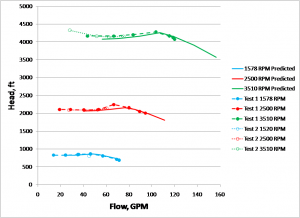
Figure 5: Measured pump performance showing head (pressure rise) versus flow (in gallons per minute).
Conclusions
All of the goals set forth in the test program were accomplished. Early in 2011, SwRI was awarded a $9.9 million award for Phase 3 to develop a multi-stage version of the cooled diaphragm and to construct a demonstration facility at SwRI. Tests will commence in 2013. This pilot scale testing will increase to technical readiness level permitting implementation in a full scale power plant.
Acknowledgments
The authors would like to thank the U.S. Department of Energy National Energy Technology Laboratory for providing the majority of the funding for this work, and Dresser-Rand and BP for additional co-funding. The contributions of Supervisor Robert Rendon and Staff Craft Technician Marc Johnson in SwRI’s Space Science and Engineering Division, who machined the compressor diaphragm components, are also acknowledged.
The Authors
Dr. Jeffrey Moore is a program manager at Southwest Research Institute (SwRI) in San Antonio, TX. jeff.moore@swri.org, www.rotordynamics.swri.org.
Andy Lerche is a senior research engineer at SwRI.
Hector Delgado is a research engineer at SwRI.
Dr. Tim Allison is a research engineer at SwRI.
Dr. Jorge Pacheco is the supervisor of the Aerodynamics-Thermodynamics Design group for Dresser-Rand in Olean, NY.

Comments