
February 2011, Vol. 238 No. 2
Features
Spread Spectrum Communications For SCADA Systems
As oil and gas companies work toward greater automation and e-business solutions, the challenges of getting real-time, reliable data from remote locations continues to be one of the greatest hurdles.
Today, there are many fine choices in electronic flow measurement (EFM) and remote terminal unit (RTU) equipment available. There are also many fine “bug-free” software programs to archive, audit, and display the collected data. The single-biggest problem remains communications. It is a commonly held belief that more than 80% of all SCADA system problems are communication failures.
To further complicate the problem, the FCC-licensed radio systems that have been the backbone of the SCADA and telemetry business for many years are becoming hard to come by. In many areas, there are no more licenses to be had. Because of the saturation of existing licenses, the FCC has re-farmed licenses to create smaller broadcast areas, less bandwidth, and smaller frequency variations allowances.
New Solution
A few years ago a new radio medium became available. This system operates on a shared frequency and is called spread spectrum. This relatively new technology offers many advantages and new versatility to SCADA operators. All spread spectrum radios share the band from 902-928 MHz, or 2.4-2.4835 GHz, and there is a now a new spread spectrum frequency being released at 5.7 GHz. It is important to remember that the higher the frequency, the less forgiving the communication path. This is to say that the higher the frequency, the more potential there is for problems from trees, hills, and buildings – even weather, at the higher frequencies, can affect the signal.
There are two types of spread spectrum radios in use in the industry: direct sequence and frequency hopping. Both technologies employ digital packet data. The data packet size is often user-selectable and can range from 9-100 bytes per packet. Frequency hopping spread spectrum radios change frequencies from two times per second to several hundred times per second, sending one packet on each frequency. It is critical that all the radios in a network are synchronized to hop to the same frequencies at the same time and in the same order.
When spread spectrum first became available, the transmit range of these radios was very limited – usually a couple of miles at most. But, as with many new tech products, the demand from industry coupled with technological advances, created a product that now can “talk” for distances of 20 miles, and in some instances are “talking” more than 40 miles without a repeater.
Information Requirements
In the oil and gas industry, custody transfer data is mission-critical information. This data cannot be lost or altered. In conventional licensed radio systems, the data is acquired through a polled response. A host computer polls its slave and requests the accumulated data. Many of these systems are limited to baud rates of 9,600 or 4,800 bits per second.

Spread spectrum radios can be set to “talk” to a host computer or EFM at speeds of 115K baud. This is 12 times faster than a 9,600 connection. In addition, the spread spectrum radios can “talk” radio-to-radio at speeds of 188K baud, regardless of what the RTU or EFM port speed is set to. Speed of the end device and radio-over-the-air speed are independent.
With some spread spectrum radios, each device in the field could theoretically be set to different baud rates, and the system would still operate normally. In today’s need-to-know economy, speed of polling time can be critical to the success of a SCADA system. In many applications, alarms and gas flow data are being gathered over the same radio network. The faster a network can gather data, the more versatile it becomes. If you have high-speed radios, you can bring back larger files, or poll more frequently.
Some digital spread spectrum radios can bring back real-time alarms during the middle of a polling cycle. The alarm packet slides through on the hopping cycle between packets of flow data. High-quality spread spectrum radios can enable store and forward operations. This is to say, the radio can act as a repeater, buffering data from other radios to be forwarded on the host.
Licensed radios are limited to one repeater in a network. This repeater is actually two radios tied together: one radio “talks” to the host, and the other “talks” to the slave sites. Every slave site must be able to transmit to the one repeater. If the slave cannot “see” the repeater, this site will not report into the telemetry system, and its information must be hand-collected.
Spread spectrum radios, where each radio is capable of acting as a repeater, can have more than one repeater in a network. Some spread spectrum radios can have unlimited repeaters in the network. This feature allows the user to “talk” around hills and mountains, or down into valleys, by using a wireless “daisy chaining” of radios. In some models, repeaters may function as slaves and repeaters at the same time, enabling repeaters to also be used as data collection points. These features can potentially reduce system costs by allowing operators to use less radio to do the same job.
Data Errors And Communication Failures
In a licensed radio system, the master polls the slave at the request of the host software package, and it is the software’s responsibility to re-poll the slave if it does not see an answer. Many RTUs and EFMs have the ability to cry out if they enter alarm conditions. But most do not know if the master has seen their alarm. Additionally, in areas where radio signal strength is weak, the slaves do not know when they call out if the data got through to the master. With spread spectrum radios, there are several ways manufacturers have compensated for these qualities.
Some spread spectrum radios have the ability to do smart retries and message acknowledgements. Now, when a message from a slave is sent to the repeater, the repeater acknowledges that it has received the message, and tells the slave to go into idle mode. The repeater now has the responsibility to get the message to a higher level. That level may be another repeater or the master radio. This repeater will continue trying until it receives an acknowledgement from the next radio in the network.
With licensed radio systems, the receiving radio had no knowledge if the data it received was corrupted. Spread spectrum radios can detect errors in the transmitted data. These radios use one of two methods for handling data errors. The first is FER (forward error correction). This is an algorithm designed to correct errors based on the mathematical probability of what the data should have been. The problem with FER is that as signal strength fades, there comes a time where more of the data is corrupt than correct, and you may actually introduce errors into the data by trying to do correction.
The second method is the use of 16- or 32-bit CRC check sums. With this method, each data packet is analyzed by the receiving radio to ensure all of the data that was supposed to be sent in fact arrived, is intact, and in the correct shape and format. If it is not correct, the receiving radio calls back to the sending radio and asks for a retry. The advantage with CRC check sums is that you have a true digital device – it either receives error-free data or it receives nothing.
System Design
An important step in choosing a radio provider is finding a company that will assist in the design, installation, and implementation of a radio network. About 80% of communications problems can be traced to poor or no design. The first step to a system design is to get the GPS readings to your provider.
The second step is to have every radio link plotted on a radio path study software program. We often hear that the proposed link is “no problem,” or “it’s a short distance across flat ground.” All too often the truth is that there are 50 or more feet of elevation change, in the form of a hill between sites, and the antenna height is 10 feet on each end. In the example just cited, there is almost no chance that the radio system will work.
After establishing the individual links, the entire network should be designed to provide the most robust and reliable system possible. Software programs will enable the designer to preplan the location of repeaters, slave repeaters (EFM sites where a radio is acting as both a repeater and a slave), and slave sites. The software should be capable of providing the user with both aerial views of the topographical area to be mapped as well as topographical cross-sectional views of the individual links.
There are several commercial software systems that can determine the signal strength between links and help determine the necessary antenna heights and antenna sizes needed to ensure communication. Preplanning the location of repeaters will save hours of frustration during installation when assumptions prove to be less than accurate.
System Operation
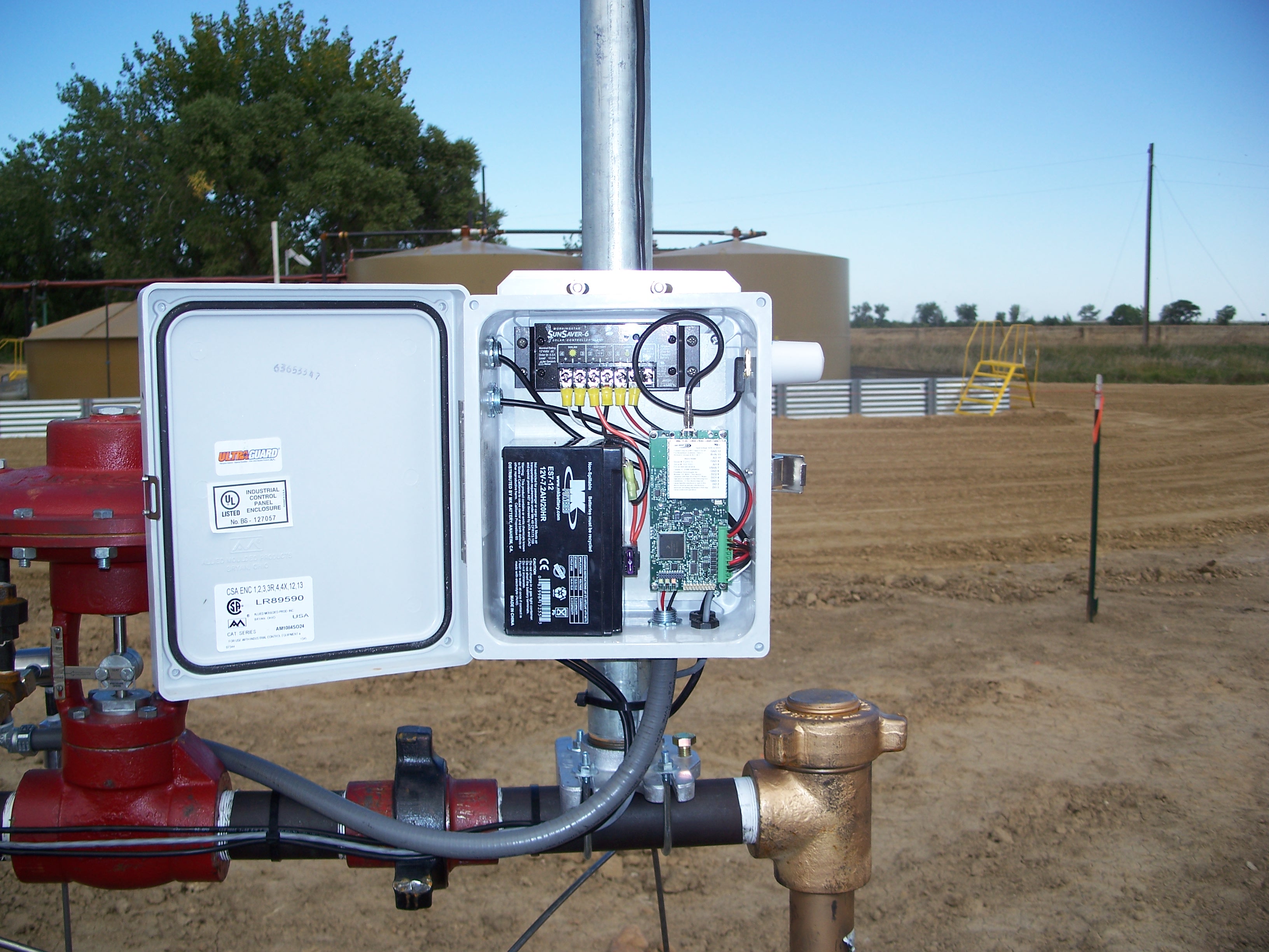
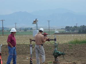
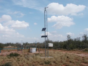
Modern spread spectrum radios are reliable and relatively low maintenance. The problem is that sophisticated electronic EFM, RTU and radio applications in the oil and gas industry require electrical power; lightning protection; and water, dust, and insect-proof environments, but must be placed in remote locations where nothing could be further from the actual operating conditions.
Good spread spectrum radios are designed to accommodate low power requirements, have built-in surge protection, and are UL (or CSA) Class I Div II approved. Yet, nothing is foolproof, and nothing can withstand a direct lightning strike. Nevertheless, consumers should look for manufacturers who provide long warranty periods, and low-cost, no-hassle replacement for radios that are damaged by lightning and other acts of God.
Most spread spectrum radio manufacturers provide diagnostic software that allows the user to see the entire network from the host computer. Some diagnostic programs can actually be run while the system is polling for data. The diagnostic packets slip through between the data packets. Since the over-the-air baud rate is 188K baud, this looks seamless to the user. By using the diagnostic software program, a technician can: 1) find out if a radio is receiving and transmitting, 2) see the temperature of the radio, 3) see the battery voltage to the radio, 4) measure the signal strength, 5) measure the background noise level, and 6) access many other important features of the radio.
One of the most troublesome problems with licensed radios was the “chirping radio.” This is a term for a radio that has hung up in transmit mode and is holding the frequency hostage by being in a continuous broadcast mode. No other radio can “talk” while this radio has the frequency, so no EFM reports are possible, and no alarms can come in. It is almost impossible to determine the location of a “chirping” radio without driving to every location and unplugging each radio until the system becomes free.
Spread spectrum radios do not “chirp” because they are hopping on many different frequencies. It is possible for the RTU or EFM to hold the radio “high,” meaning it is being told to continuously broadcast. By using the spread spectrum diagnostic software, this radio can be located and isolated from the network. This can be done from the host computer, eliminating the need to drive to every location. In other words, the radio can be taken off line remotely.
Spread spectrum radios can easily be maintained by field technicians familiar with normal RTU or EFM operations. These radios can be set up, installed, or replaced in a few moments, using a laptop computer and a screwdriver. Many radios only require a four-wire connection; these connections are power, ground, transmit and receive. Most host software packages will generate alarms if data is not received at predetermined times, triggering the technician to run the diagnostic software.
Licensed radios were designed to operate in an interference-free environment. When a licensed radio encounters interference, it can cause lost data or corrupted data. In today’s SCADA world, where in many areas licensed frequencies are mostly taken, there is a greater chance of encountering interference on your frequency than previously. The spread spectrum radios expect to find interference and are designed to operate in an atmosphere where they must share the frequency.
Expected Results
As with any communication system, a well-designed spread spectrum radio system should be capable of generating reliable measurement data and real-time alarms from remote locations. By FCC regulation, spread spectrum radios can only emit one watt of power at the radio. This can be boosted to four watts of radiated power at the antenna (again regulated by FCC rules).
Licensed radios can use much higher output power (five watts at the radio), but spread spectrum can be used in multiple repeater patterns to provide equal or greater signal coverage over long distances. It is reasonable to expect spread spectrum to be able to provide service equal to or better than licensed radios. Spread spectrum radios do not need licenses (which are not available in many locations), so there are no recurring fees, or monthly service charges.
Spread spectrum radios are faster, and allow quicker polling times than licensed radios. A system of spread spectrum radios will normally have fewer radios than a licensed radio system, because licensed radios require two radios to make a repeater. Many spread spectrum radios can be programmed to be a master, a slave, or a repeater, allowing the operator to stock fewer spare parts and make replacement much simpler.
Hybrid Communication Systems
One of the qualities of spread spectrum radios that many oil and gas companies have found endearing is the ability to “tail-end” spread spectrum onto other communication mediums. The two most common tail-end additions are to add spread spectrum to licensed radios and to combine spread spectrum to cellular digital packet data (CDPD) modems. In a licensed radio system, spread spectrum can be added by putting a licensed radio “back-to-back” with a spread spectrum. This can be done by hooking the two radios together with a hard-wire connection, between their RS-232 ports. This creates a licensed-radio-to-spread-spectrum repeater.
The tail-end connection to a CDPD is done the same way, connecting the RS-232 ports of both devices. With a CDPD tail-end connection, it is possible to jump over hundreds of miles to a CDPD site from the host, and then to poll a group of sites in a given area on the spread spectrum system. Since all the radios are coming back to one CDPD, this means only one CDPD monthly charge for all of the sites. By purchasing one of the “all you can eat” menus for the single CDPD site, it is possible to bring back dozens of sites for as little as $50 per month in total cost.
Conclusion
Just as there are many tools needed to build a house, there are many tools needed to build an enterprise-wide communication solution. In challenging terrain or areas where there is a large population of EFM or RTUs, spread spectrum can provide a robust, reliable solution.
Spread spectrum is not a good choice when communication over very long distances (i.e. 40-100 miles) is needed. There are times when satellite, CDPD, or landline will all have advantages over spread spectrum. In the evolution of data collection in the oil and gas business, spread spectrum is a relatively new technology. All new technologies suffer from a lack of understanding, and there are many misunderstandings about spread spectrum radios. Here are a few:
• “Spread spectrum cannot use as much radiated power as a licensed radio, therefore it can’t be as good!” True, it does not have the same power, but it can accomplish the same results by using “daisy chaining,” and by using CRC check sums.
• “Spread spectrum radios share their channel with all other spread spectrum radios, so you can’t trust them to get alarms!” This is partially true; it does share the frequency. But spread spectrum was built to handle interference, and has 32-bit check sums and auto-retries to resolve conflicts, giving operators better assurance of data delivery.
• “Spread spectrum cannot be used when there is an existing licensed radio system!” This is not true. Spread spectrum can be added to existing licensed radio systems to create additional repeaters, and add versatility to existing systems.
• “Someday there will be too many spread spectrum radios, and then none of them will be able to ‘talk’ since they share the frequency!” False again. In some areas of the country, there are huge spread spectrum networks, working effectively every day. In the oil and gas business, examples can be found in Gillette, WY and in Farmington, NM. In each area, there are complicated spread spectrum systems consisting of more than 5,000 radios, all polling for EFM data multiple times per day, and delivering error-free data.
It may be important to remember that EFM was new technology not so many years ago, and there were many operators who could never have imagined the thousands of EFMs that are in use today. As the automation revolution continued, there were those who could never have envisioned the use of licensed radios to collect data from remote locations. Now, spread spectrum radio is the “new kid on the block.” When we look back some years from now at the continuing evolution of data collection, what will be the new technology we will be comparing to our trusted old friend, the spread spectrum radio?
Author
Jim Gardner is the oil and gas team leader for FreeWave Technologies, Inc. Prior to joining FreeWave, he was vice president at Remote Operating Systems. He graduated from the University of Washington in 1975 with a B.A. degree and is a member of ENTELEC, ASGMT and ISHM.

Comments