
October 2010 Vol. 237 No. 10
Features
Finding And Mitigating SCC On An Oil Pipeline In Mexico
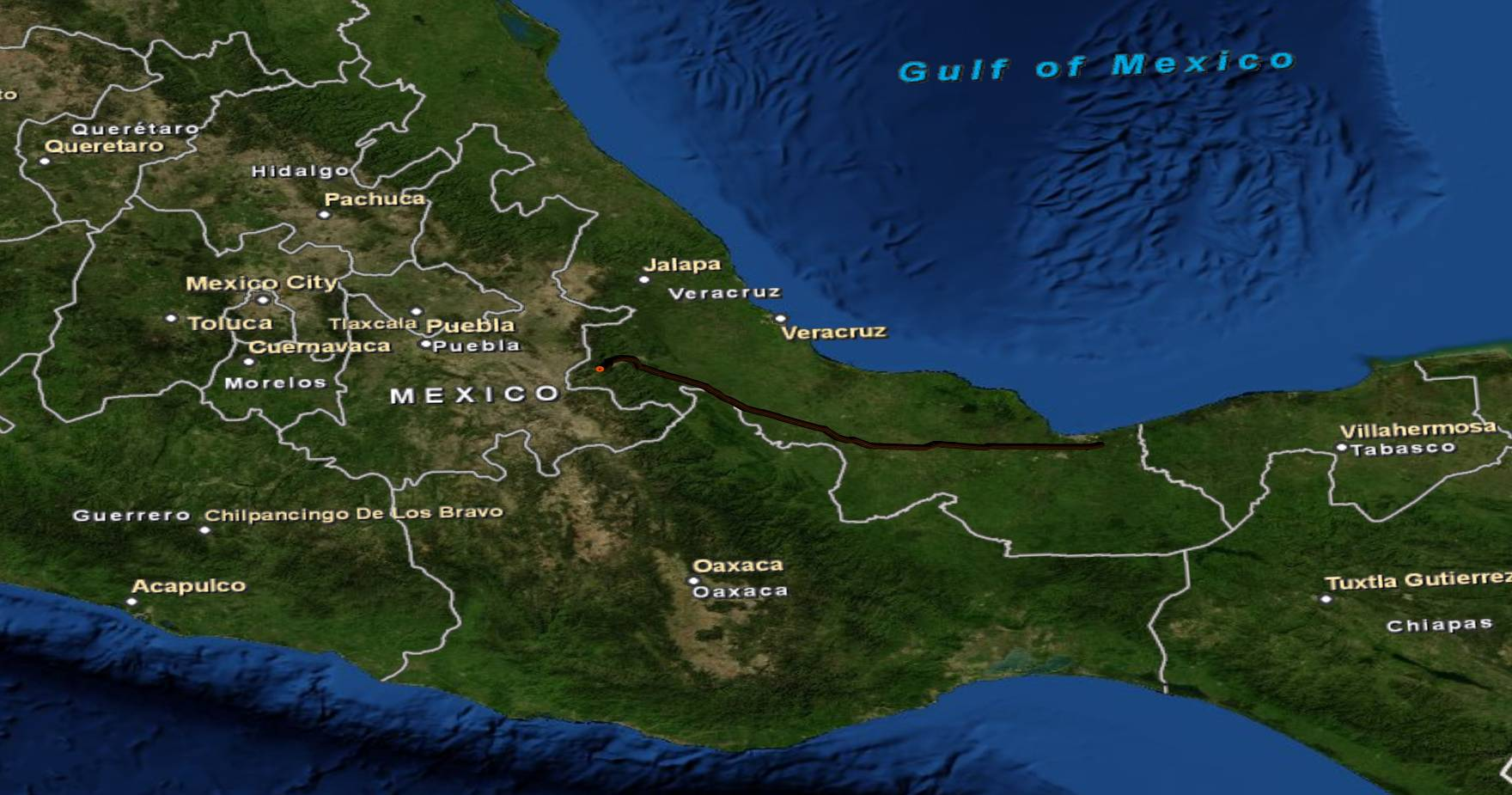
To identify and mitigate the presence of stress corrosion cracking (SCC) in a 30-inch, 340-km oil pipeline owned and operated by Pemex Refinación, a plan was developed and executed by Weatherford Pipeline & Specialty Services (P&SS) and Pemex Refinación.
The pipeline, located in the Mexican state of Veracruz, was built in 1979 using API 5L X65 pipe. It transports between 350,000-400,000 bpd to the Tula and Salamanca Refineries. Weatherford’s scope included inline inspection (ILI) to detect stress corrosion cracking (SCC), internal and external corrosion and mechanical damage.
This integrity project required a unique approach because little or no work concerning SCC had previously been undertaken in Mexico, thus the expertise to actually confirm and verify the existence of SCC, along with the ability to accurately measure it once found, was not readily available. To meet Pemex’s needs, Weatherford assembled a group of knowledgeable industry experts as part of the integrity team.
Chemical Cleaning
A procedure was designed to ensure the pipeline’s inner surface would be clean enough for a successful inline inspection while minimizing disruption to normal operations. Weatherford P&SS used its proprietary chemical compound Superclean® 2001 and a specially designed online cleaning procedure to ensure the inside wall of the pipe would be free of paraffin and other crude oil residues that could prevent the UT sensors in the crack detection tool from detecting the potentially dangerous anomalies.
Working closely with Pemex field engineers, Weatherford adapted the chemical-cleaning procedure to their specific needs, taking into consideration their delivery schedules to avoid interfering with normal operations. An extensively revised procedure was prepared for each of the pipeline’s six sections. Equipment included two large triplex pumps used for loading the cleaning pigs and injecting the chemical batches into the pipeline.
Superclean® 2001 was run in batches mixed with diesel and contained between cleaning pigs. The pigs, pipeline debris and chemical batches were collected at each receiving station and analyzed to determine the level of cleanliness obtained.
![]()
Figure 3: Typical Cleaning Batch.
The movement of equipment used for the chemical cleaning stage from one section to the next was challenging, given the tight schedule, and especially considering that the inspection tools had to be run immediately after each cleaning. Strict safety measures were implemented by Pemex and Weatherford and a rigorous plan for management of resources was put in place, ensuring successful execution of this stage of the project.
Inline Inspection
Inspection tools were run immediately following the chemical-cleaning stage, starting with the MultiCal 360TM calliper tool. The MultiCal was used to determine the presence of any deformations, ovalities or out-of-round conditions that could be considered injurious to the pipeline and/or detrimental to the safe passage of the other inspection tools as well as having an onboard Inertial Mapping Unit for the localization of defects via GPS from all ILI runs.
Following the MultiCal, a high-resolution MFL (magnetic flux leakage–axial) tool was run in each section to determine the presence of any metal loss, corrosion or other metallurgical type anomalies and/or irregularities.
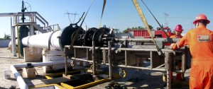
Figure 4: MFL Tool Launch.
The UTCD (ultrasonic crack detection) was the final ILI tool to be run. It is an extremely sophisticated device, capable of detecting and measuring fine longitudinal cracking such as SCC. UTCD has been extensively used to identify critical, and even to a large extent, sub-critical SCC. SCC is considered to be an environmental phenomenon and can occur as a single crack or as a colony of cracks; single cracks though, can grow in length and coalesce with others to produce much longer, wider cracks and eventually leaks and pipeline ruptures.

Figure 5: Ultrasonic Crack Detection Tool Launch.
All information collected by the ILI tools was stored in a single database that allowed comparisons among the different inspection technologies used. This allowed analysts to easily compare data between technologies and provide greater clarity on anomalies, enabling better-informed decisions on corrective and possible preventative actions required.
SCC Direct Assessment
The employment of Direct Assessment (DA) techniques acted as further confirmation that all possible methodologies in finding SCC had been utilized and the subsequent results cross-correlated, as well as investigating the type of SCC found and the origins of this type of anomaly.
Using DA techniques, the most likely locations for SCC were determined for all six sections of the oil pipeline. These were subsequently excavated and directly assessed using a specifically designed procedure where all relevant conditions related to the pipeline and its environment were noted. The selected dig sites in the first four sections confirmed that SCC was not present as reported by the ILI runs. In the last two sections, SCC was found in some of the dig sites which correlated with what the UTCD tool had reported.
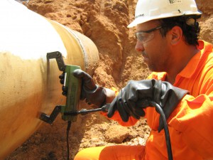
Figure 6: SCC Direct Assessment.
Lab Testing
Samples of the failed pipe taken from this same pipeline system where SCC was present were sent to a metrological laboratory for further investigation. The tests included: metallographic examination, microhardness testing, scanning electron microscope (SEM) examination, tensile testing, fracture toughness testing, impact testing and chemical analysis.
After analyzing the direct assessment and the results from the lab tests, it was concluded that SCC was caused by a high pH in the soil (High pH SCC) and that the defect growth was 0.3 mm/year.

Figure 7: Sample of Failed Pipe.

Figure 8: Photomicrograph Showing a Crack.
Assessment
The application of the assessment criteria (methodologies: Risk Management, Fitness for Purpose and Integrity Assessment; standards: ASME B31.G, Modified B31.G, PCORRC, RSTRENG-2 and LPC-2) to all of the analyzed and interpreted data recorded, by the three technologies, ultimately led to a determination of the most appropriate rehabilitation process to be employed for each specific defect type. Investigative work was undertaken to gather, classify and assess past information including ILI reports, previous repair data, maintenance and operation programs etc. Databases were built to compare and analyze past and new information side by side.
Rehabilitation
The rehabilitation work was an essential part of this project and was carried out with minimal interruption to normal operations. Most of the SCC defects were repaired with compression sleeves which were installed with the pipeline in normal operation while external corrosion defects were repaired using Weatherford-designed composite sleeves. Composite sleeves address both axial and circumferential anomalies including cracks, girth welds, seam welds, dents, gouges, galling lamination and corrosion. Only two cut-out repairs were required on this project.
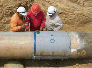
Figure 9: Rehabilitation Using Compression Sleeves.
Internal Corrosion Assessment
The MFL inspection exposed growth of internal corrosion in some areas when compared to a previous ILI inspection performed 11 years ago. Pemex wanted to know the potential cause of this corrosion, as well as the proper mitigation recommendations, thus an additional assessment was performed. It was concluded that oxygen was being injected into the line through surge tanks and that microbiologically influenced corrosion (MIC) may be associated. Figure 10 shows a comparative graph taken from the Internal Corrosion Report.

Figure 10: ILI Inspections Comparison.
Water Hammer Analysis
The majority of SCC defects found were located in Section 05 of the pipeline where three SCC-related ruptures have occurred in the recent past. Pemex also foresaw the need to increase the flow in this pipeline due to increasing demand in their refineries fed by this pipeline system. A pressure transient analysis was needed to check the possibility of increasing the transport capacity up to 100,000 bpd without the risk of another failure.
The analysis revealed that the first 9 km of Section 05 had to be replaced with a heavier pipeline in order to eliminate the risk of a water hammer that could potentially cause a rupture with the expected new throughput.
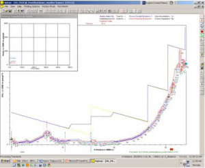
Figure 11: Pressure Transient Simulation.
Conclusion
This project saw a different approach taken to pipeline integrity as it was designed to include more than just an assessment based primarily on an ILI report. The concept expanded on a good initial idea, matching ILI and DA, and ended up investigating all possible root causes of the major integrity threats identified along the way. Future transport requirements were also considered and a new scope of work devised to accomplish a higher demand of oil delivered to the refineries. This can be evaluated against the cost of building a new pipeline with a greater transportation capacity.
Similar and more complex integrity/assessment/rehabilitation projects like this will become common practice as increasing demand is put on existing transport networks, not forgetting heavier crude oils flowing through older pipelines.
Authors
Ignacio Castro is ILI Project Manager for Weatherford P&SS Mexico.
Luis Sánchez Graciano is Pipeline Transportation Manager for Pemex Refinación.

Comments